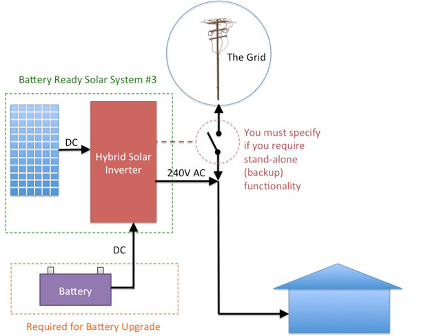
In our case it is obviously stand alone. At the same time the inverter neutral output goes to the same earth bar.
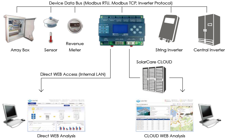
Modbus Wiring Diagram Solar Inverters Blog Alliance Solar
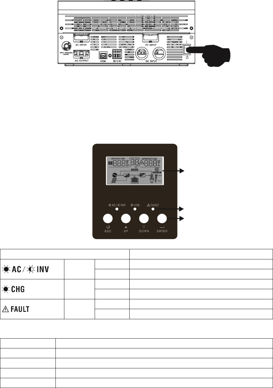
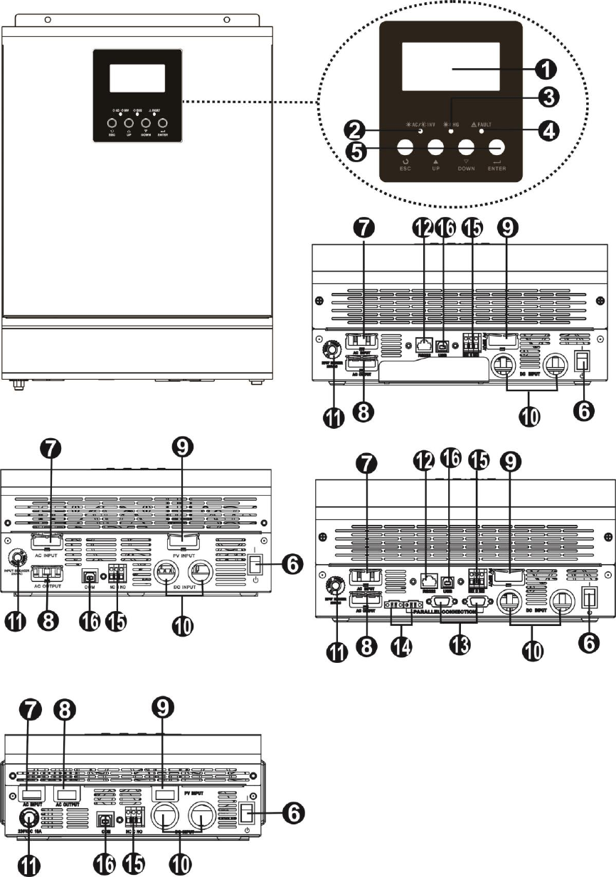
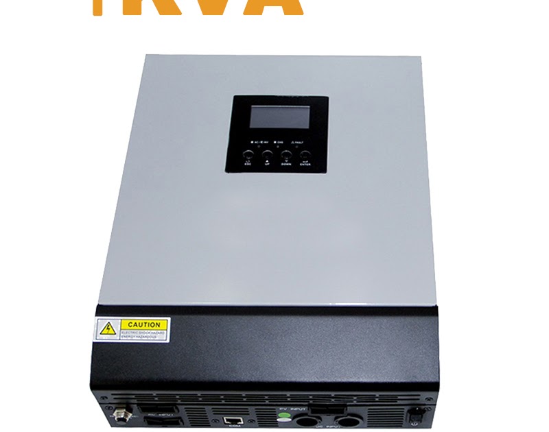
Axpert inverter wiring diagram. Its comprehensive lcd display offers user configurable and easy accessible button operation such as battery charging current acsolar charger. This is a multi function invertercharger combining functions of inverter mppt solar charger and battery charger to offer uninterruptible power support with portable size. So as per my opinion choose a pure sine wave inverter. It may be grid tied or stand alone. Its comprehensive lcd display offers user configurable and easy accessible button operation such as battery charging current acsolar charger. 500mm 500mm 500mm 500mm 500mm 500mm 500mm note.
Rating of inverter. 1 the junction box at the pv array wiring from pv array to the disconnect switch on the house the disconnect switch the wiring from the disconnect switch to the circuit breaker panel. I have installed axpert ks 3 kva inverter in my home. For proper air circulation to dissipate heat allow a clearance of approx. What is the reason and how to fix it. I am not sure but it looks like the inverter neutral is bonded to earths the inverter earth and the earth coming from mains.
The power rating should be equal or more than the total load in watt at any instant. I did the wiring in this order. Put wire cover back to the unit. Only inverter phase out is connected to appliances and it is working ok. I saw the same thing looking at the diagram. Its comprehensive lcd display offers user configurable and easy accessible button operation such as battery charging current acsolar charger.
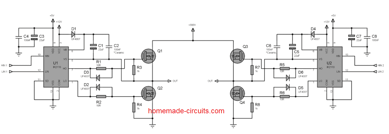
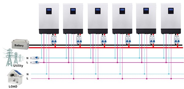
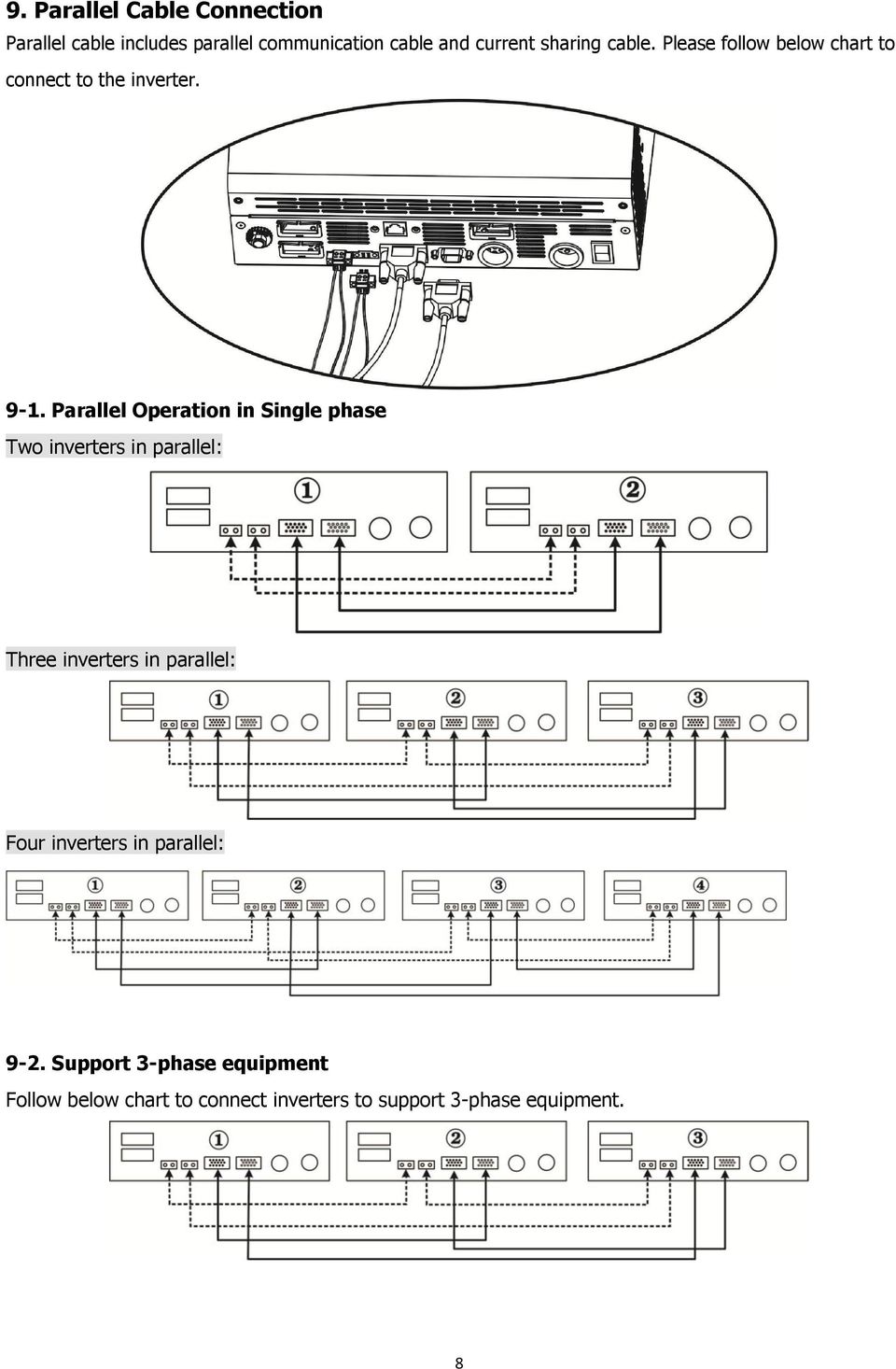
I remove this inverter and install axpert 32 kw vmiii inverter using phase out method it works well if there is electricity but appliances stop when electricity goes off. The enphase wiring diagram is here. In line mode the inverter can convert power from gird to bus for charging the inverter circuit of axpert series is based on a full bridge circuitry and its output is driven by photo couplers. Typically modified sine wave inverters work at lower efficiency than pure sine wave inverters. Mounting the unit when installing multiple units please follow below chart. Here is a very simple diagram of the micro inverter system.
33 inverter full bridge the inverter circuit figure 33 and pwm control are can both active under battery mode and line mode. This is a multi function invertercharger combining functions of inverter mppt solar charger and battery charger to offer uninterruptible power support with portable size. Now the inverter is providing parallel operation function. This is a multi function invertercharger combining functions of inverter mppt solar charger and battery charger to offer uninterruptible power support with portable size. Automatic ups system wiring diagram in case of some items depends on ups and rest depends on main power at office or home. 50 cm to the side and approx.
How to wire solar panel to 220 v inverter 12v battery 12vdc load and 220v ac load220v fan light etc ac dc load. The inverter input earth and output earth go to the same earthing bar. Manual ups wiring diagram with change over switch system.
Gallery of Axpert Inverter Wiring Diagram