Reloc modular wiring solutions for lighting control and power distribution systems provide numerous advantages to contractors building owners and facility managers. All feature full 20 20k 15db frequency response.
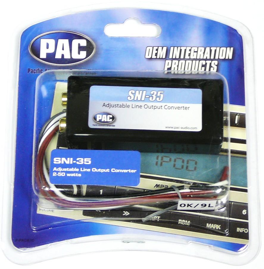
Pac Sni 35 Variable Loc Line Out Converter
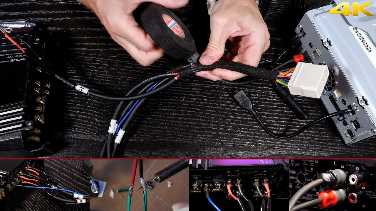
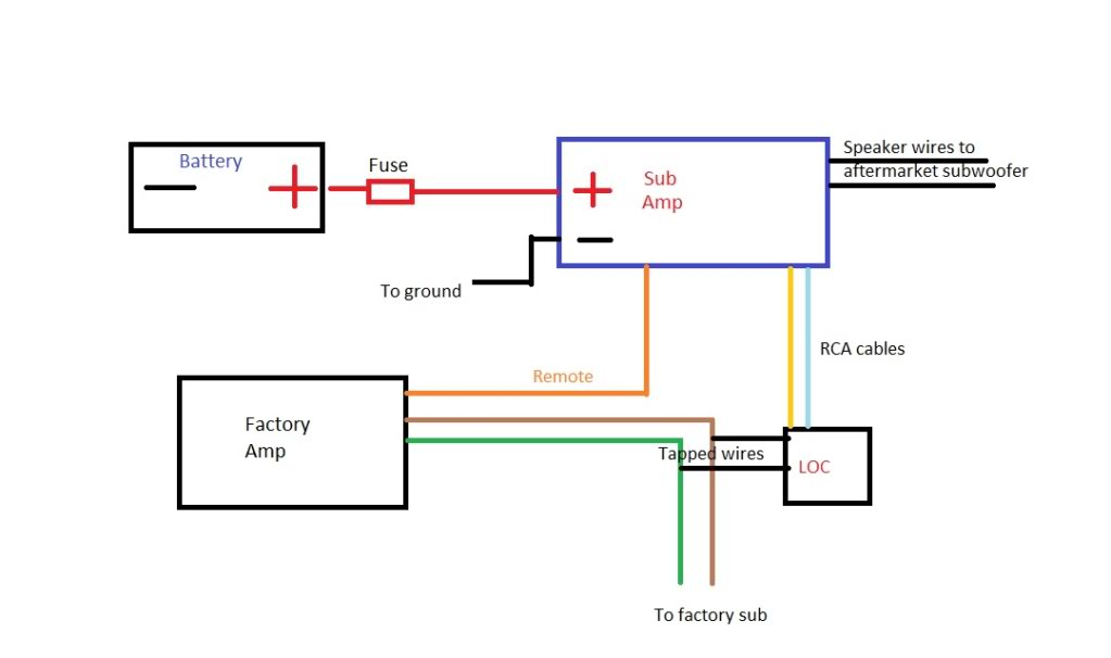
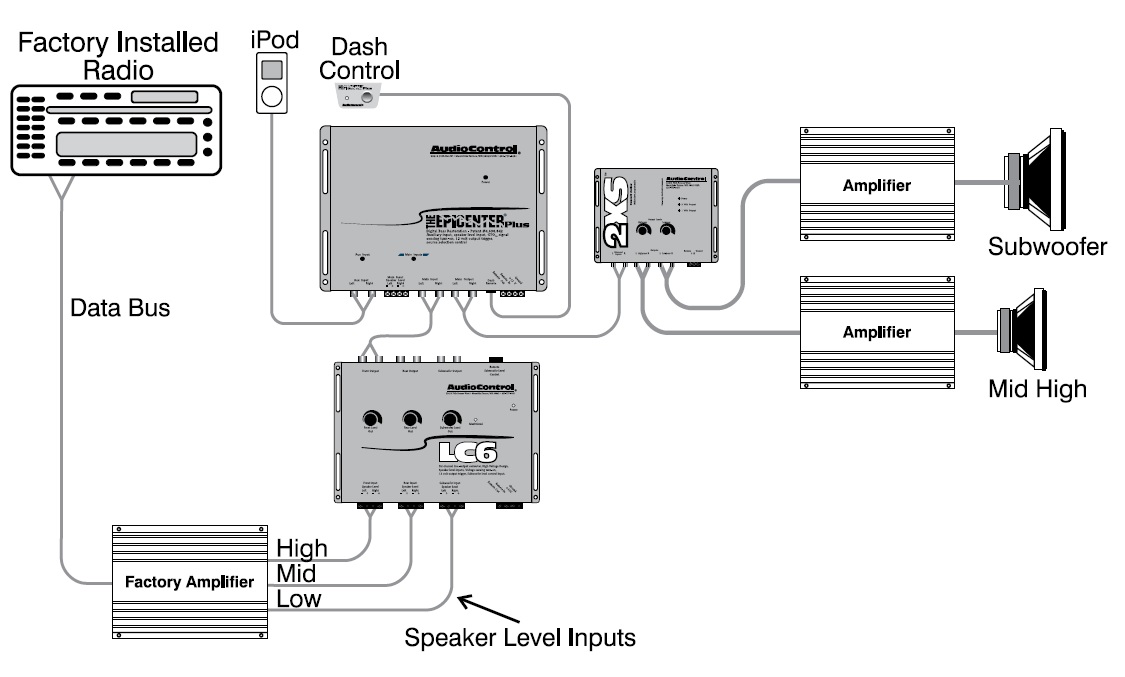
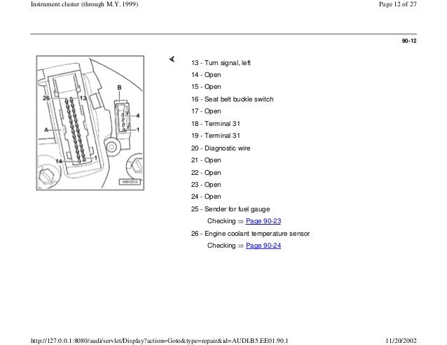
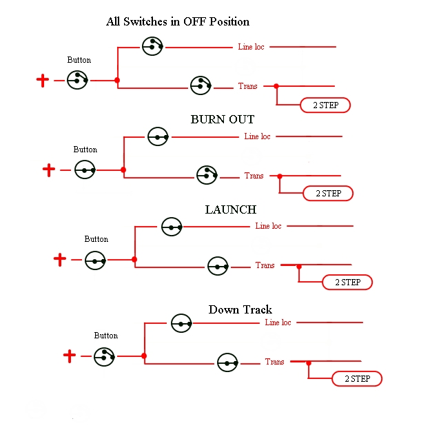
Loc wiring diagram. Pacs locpro redefines the line output converter. The loc should be installed on a stereos speaker output wires or the output wires on an oem amplifier of up to 80 watts per channel. Some amps have that feature built in called speaker level. I disliked the large red bulb supplied with the hurst kit so i wired it to light the factory brake idiot light in the dash instrument cluster. How to wire alpine 445u lc2i loc and subwoofer complete wiring guide duration. Wiring diagrams 1 2 tech support hotline.
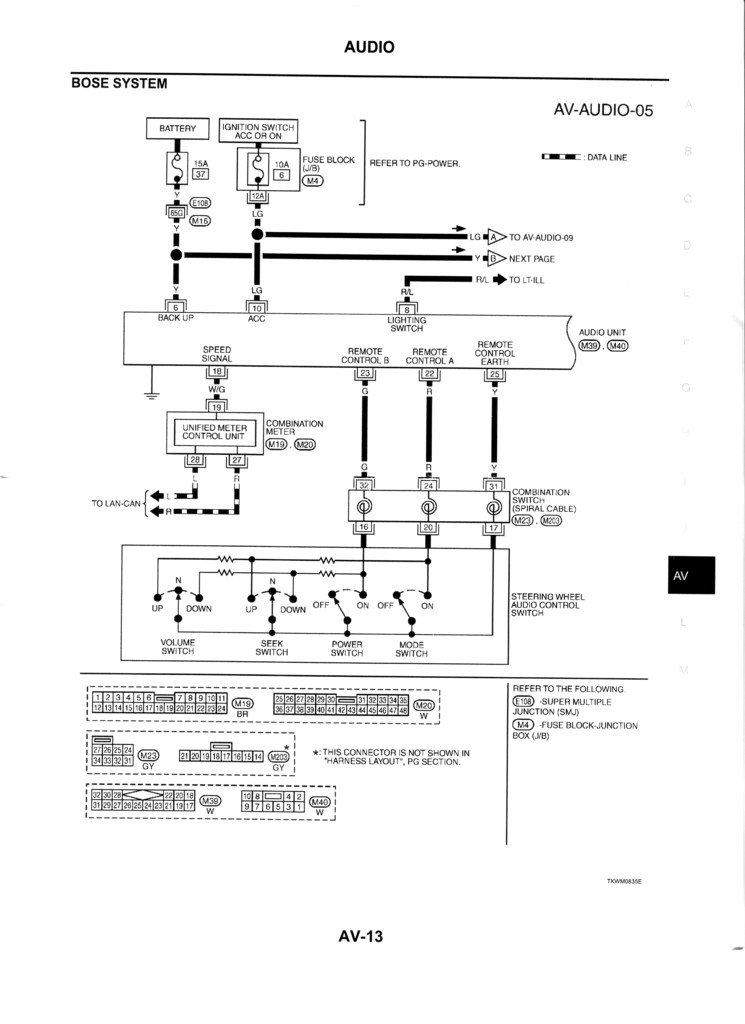
5036931918 wwwautoloccom actuator mounting 1. 5036931918 wwwautoloccom tech support. 4 ohm mono is equivalent to 2 ohm stereo. Loc wiring diagram wiring diagram is a simplified satisfactory pictorial representation of an electrical circuit. Check the amplifiers owners manual for minimum impedance the amplifier will handle before hooking up the speakers. It shows the components of the circuit as simplified shapes and the talent and signal contacts in the company of the devices.
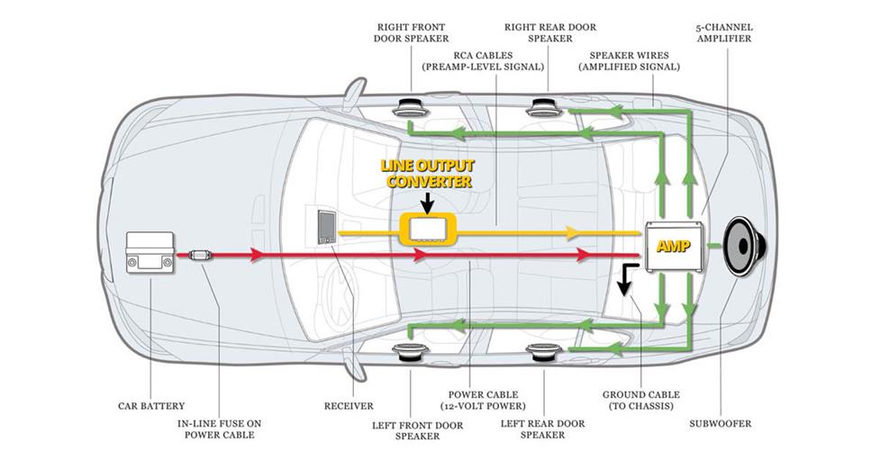
All the wires depicted in the subwoofer wiring diagrams are speaker wires. The systems pre manufactured plug and play components quickly snap together significantly reducing time and labor costs at installation. Reconnect battery and test for correct operation. Below is a picture of my hurst line lock and a diagram of how i wired it. I tapped the power at the parking brake switch and. Orlando you can use a line output converter loc to get signal from your factory speaker wiring to use for your sub amps input.
Avoid these 5 common car audio noob mistakes. Line lock wiring this site is best viewed in 1024x768 resolution. Unique stereo gain controls and universal harnessin the palm of your handdesigned from the ground up to offer more flexibility and improved. Boost shutter 34247 views. Remove all the handles fittings and arm rests from the door. Brakes are now locked.
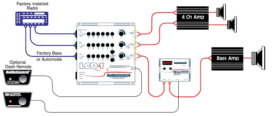
Professionally engineeredengineered to optimize audio levels between radio and amplifier to achieve the best audio performance and avoid noise. They show a typical single channel wiring scheme. Wire per diagram on next page. For wiring subwoofers we recommend using wires of 12 to 16 gauge in size. Remove the doors interior panel by inserting a screw driver between. Depress brake pedal and hold depress control switch and hold release brake pedal.
The following diagrams are the most popular wiring configurations when using dual voice coil woofers. All wiring connections should be soldered and covered with shrink sleeving. Please refer to the wiring diagram for the input connection details. These wires can be found behind the stereo in the dash on the output of an oem amplifier or on the input terminals on the oem speakers.
Gallery of Loc Wiring Diagram