If you buy the mopar performance electronic ignition system it comes with extensive instructions wiring diagrams and other information. The job of the ballast resistor was to inhibit current to a level that would not overheat the coil.
Ford Ignition Coil Wiring Toyota Www Brillenstudio Weichert De
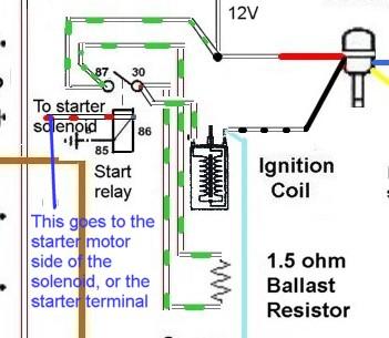
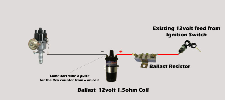
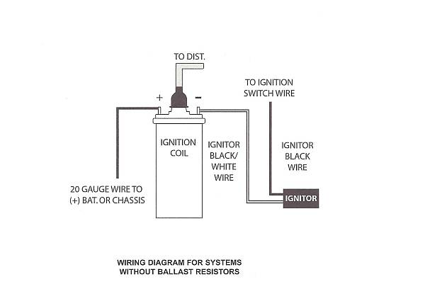
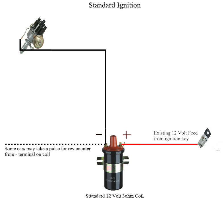
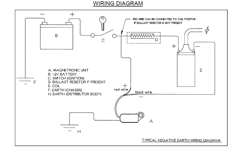
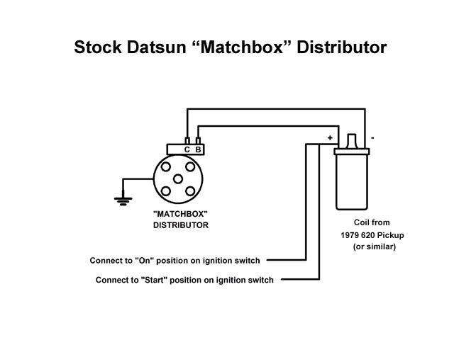
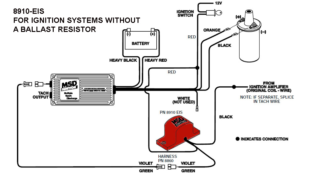
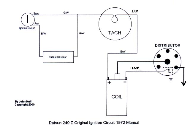
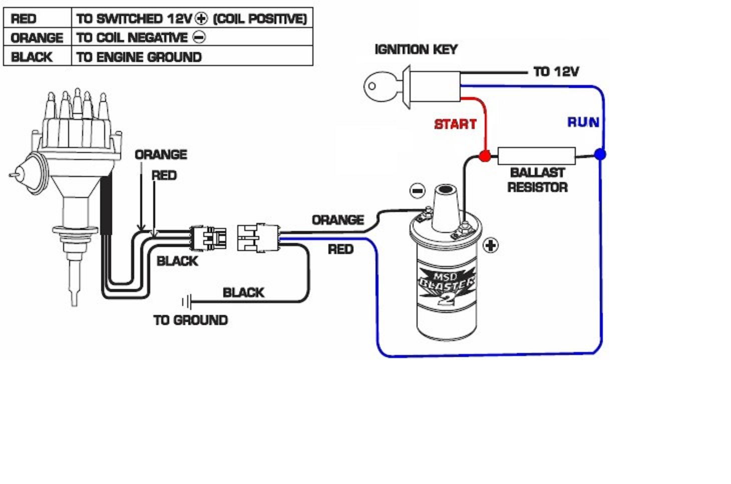
Ignition coil ballast resistor wiring diagram. In the years when engines were a lot easier to work with a ballast resistor was used in order to prolong the life of the coil. Autorestomod manic mechanic gasoline media 211241 views 1719. The purpose of an ignition ballast resistor between the ignition switch 12v and the ignition coil positive terminal is to restrict current flow. The typical automotive ignition system prior to 1974 consisted of a coil and ballast resistor with breaker points to interrupt the current flow when a spark was needed. As a matter of fact a bad diode trio in a conventional alternator can do the same damage. How to wire mid 1970s through mid 1980s ignition systems retrofitting electronic ignition on vehicles that originally had points.
How to install a pertronix ignitor ignition system classic car episode 280 autorestomod duration. Ignition coil ballast resistor wiring diagram welcome to my internet site this blog post will certainly discuss concerning ignition coil ballast resistor wiring diagram. This simple system is easy for even the novice mechanic to wire. Some brands utilized a resistor in the coil or a resistor wire hidden in the wiring from the ignition switch but mopar put their resistor or ballast resistor on the firewall or inner fender.
Gallery of Ignition Coil Ballast Resistor Wiring Diagram