See hurst roll control operation for competiton use caution. De activate switch off arming switch when the hurst roll control is not in use to prevent accidental engagement.

Dc4 Hurst Roll Control Wiring Diagram Wiring Library
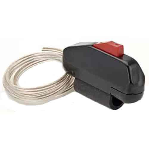
Hurst roll control wiring diagram. Arm the hurst roll control system by depressing the rocker arm switch to the on position the engage button switch should illuminate. It is a normally open momentary contact quick release switch with a maximum 10 amp. Depress brake pedal and hold depress control switch and hold release brake pedal. All wiring connections should be soldered and covered with shrink sleeving. Following the wiring recommendation properly will prevent accidental engagement of the hurst roll control system. The fuse can protect the electrical system in the event of a short circuit.
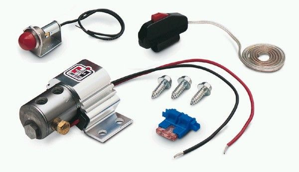
For added safety two switches arming and activatiois kit. To release brakes release. Rigorous testing has proved a 1100000 of a second release time and vibration tests have seen up to 30 gs applied without mechanical failure. Reconnect battery and test for correct operation. Complete the next steps within 60 seconds. Pistol grip roll control switch the pistol grip quarter stick shifters come equipped with a precision snap action 12 volt switch that is ideal for operating the hurst rollcontrol nitrous oxide systems trans.
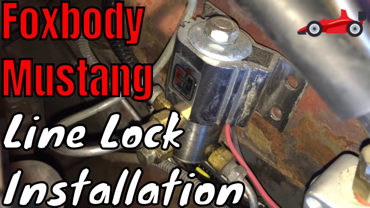
The hurst rollcontrol is used primarily in drag racing to provide positive locking action to the front wheels of race cars reducing the chance of rolling the lights and producing more effective burn outs for heating up the tires. Disconnect negative battery terminal. The hurst roll control solenoid valve is designed for 12v dc operation only. The hurst roll control solenoid valve is designed for 12v dc operation only. See wiring diagram for wiring details and should be incorporated into the wiring circuit. Holding the solenoid valve closed for more than 60 seconds can cause the fuse to burn out perma nently damaging the solenoid valve andor result in other damage.
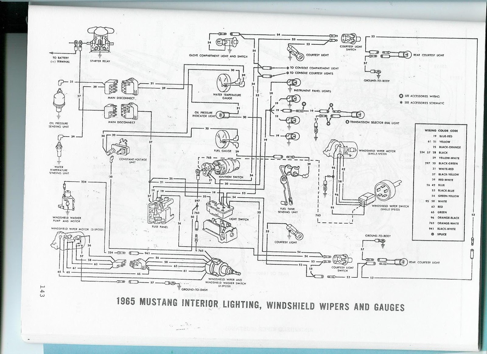
For added safety two switches arming and activation are provided in this kit. With the vehicle staged fully depress and hold the brake pedal. Installed hurst roll control wiring installation note. To actuate the hurst rollcontrol system launch control automatic vehicles only. Brakes are now locked. The other diagramnot above in the manual is clear for color codes and order.
Suggested ground and 12v source. The wire from the lamp 2 wire from the roll control switch and 4 wire from solenoid valve. Following the n are provided in th wiring recommendation properly will prevent accidental engagement of the hurst roll control system. The diagram shows a to the right of the solenoid and the solenoid has a red wire but it doesnt get wired to positive hot battery until after it goes through the momentary switch then master toggle then fuse. Hurst roll control installation instructions 5671517 2008 2010 challenger srt8 w 4 port system. Wire per diagram on next page.
Using a length of 18 gauge wire splice one end to the 3 wire of the rollcontrol switch and con nect the other end to a switched positive terminal so that the rollcontrol is only operable with the ig nition turned on.
Gallery of Hurst Roll Control Wiring Diagram