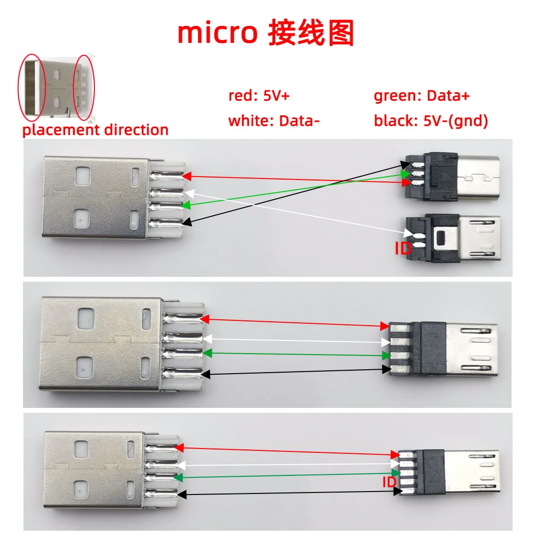
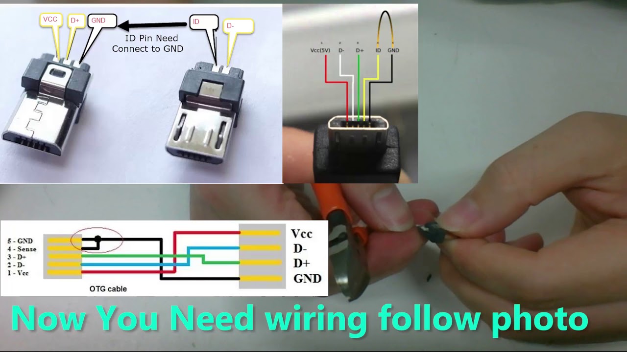
All current mobiles laptops desktop pc. Typically it utilizes black black red and white cable colors.

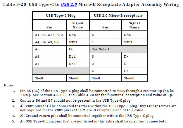
Adapt Existing Usb 2 Otg Device To Usb C But Use Usb 2 Mode
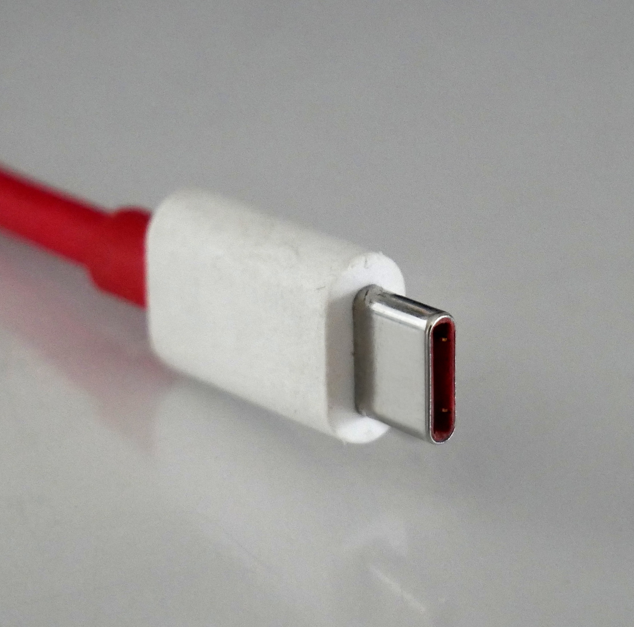
Usb c otg wiring diagram. I micro a usb 11 to 2. I make usb cables usb a to mini or micro primarily but dont have any experience with usb c. Usb plug wiring diagram usb adapter wiring diagram usb 20 cable diagram usb to rs232 cable wiring diagram usb microphone wiring diagram usb pin diagram usb connections diagram samsung usb cable wiring diagram micro usb diagram usb b wiring usb to serial wiring diagram usb hub circuit diagram usb front panel wiring diagram usb wire. I would like to create a cable that has a usb a 20 connector on one end and a usb c connector on the other mainly for connecting keyboards to cpus and charging devices. Developed at roughly the same time as the usb 31 specification but distinct from it the usb type c specification 10 defines a new small reversible plug connector for usb devices. The red one is to get sure wire with dc ability of 5 volts.
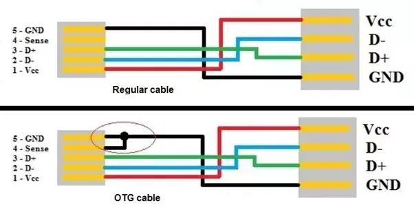
I made another schematic how you should wire things up so the usb will work as a host or otg mode. Black wire serves as ground just like in any other apparatus. Previously in mobiles now discontinued. Ii micro b usb 11 to 2. A lot of people wonder why have micro usb 5 pins instead of 4. Actually the extra pin or pin 4 is typically not connected in the normal usb cable but if it is connected to ground pin the phone will turn in a host mode and will be able to read.
Sep 13 2018 otg usb cable wiring diagram. In accordance with wiring diagram for otg usb there are just four wires used inside the cable. The type c plug connects to both hosts and devices replacing various type b and type a connectors and cables with a standard meant to be future proof similar to apple lightning and thunderbolt.
Gallery of Usb C Otg Wiring Diagram