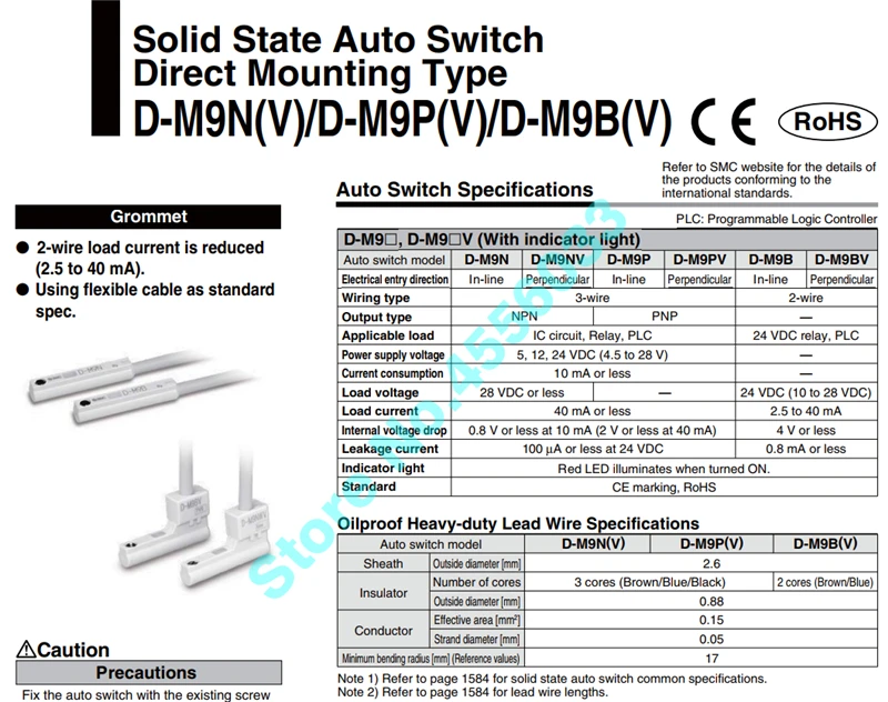
Programmable logic controller refer to smc website for the details of the products conforming to the international standards. Validated d m9 components according to iso 13849.

Wrg 5624 3 Wire Reed Switch Wiring Diagram
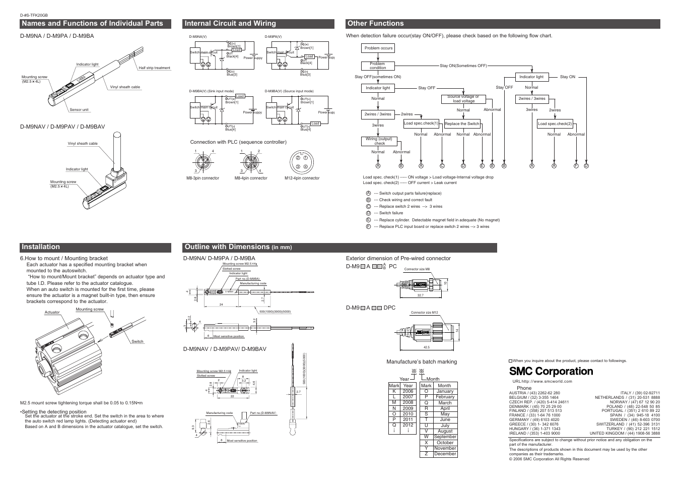
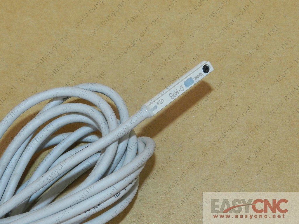
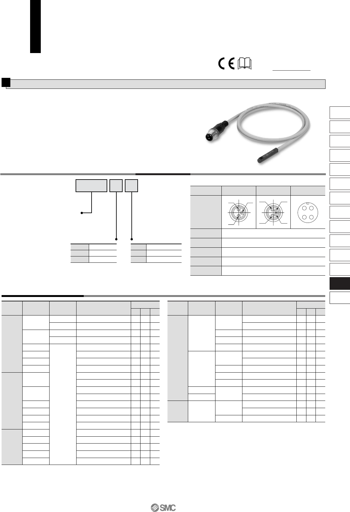
Smc d m9p wiring diagram. Smc smc d m9p d m9 3 wire solid state auto switch for use with cg1 cj2 cm2 cq2 mgp mh mx nca1 and ncq2 cylinders 05 m lead direct mounting 28 vdc 40 ma 000. D m9p from smc corporation at allied electronics automation. Email item price. Connection and current caution the maximum piston speed is. Series image for reference only. Complies with the basic safety principles in accordance with iso 13849 load operating time ms explosion may result.
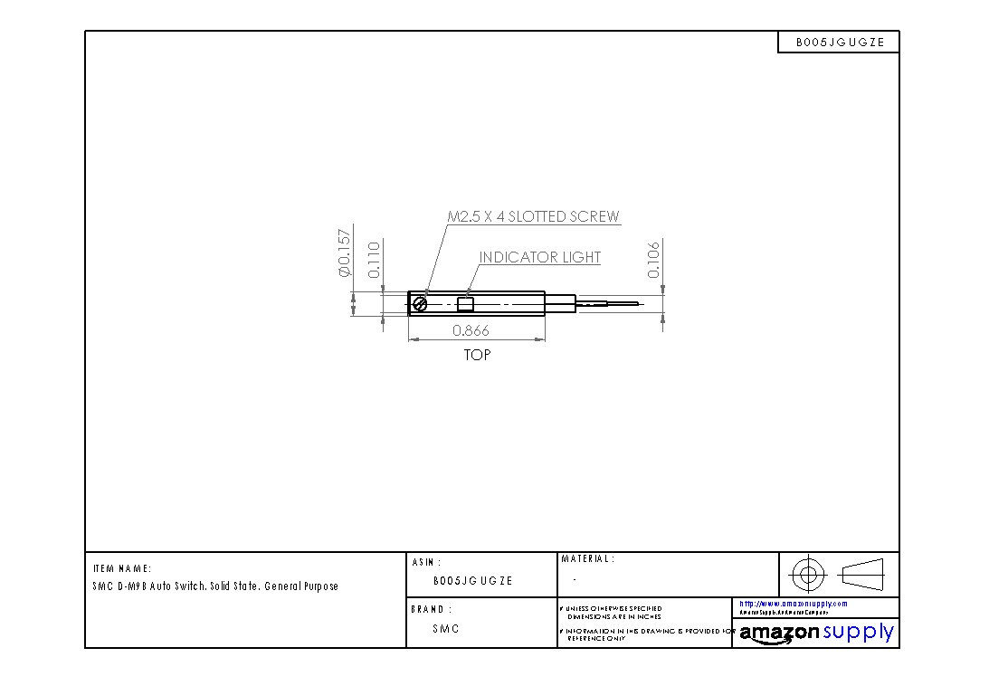
Smc d m9p auto switch auto switch accessory part number. M25 x 4 l 27 22 26 4 28 32 6 slotted set screw indicator light most sensitive position electrical entry. Page 1 4 be sure to confirm the load condition eg. D m9n in line d m9p in line d m9b in line npn pnp 28 vdc or less d m9 d m9 v with indicator light plc. Series d m9n d m9p d m9b 1 wiring should be kept as short as possible. Series image for reference only please pull down this page to review full catalog specifications pdf.
Series d m9n d m9p d m9b value before power is supplied. 1 wiring should be kept as short as possible. One type of proximity switch is an enclosed reed switch that is activated by a permanent magnet mounted to the piston. Auto switch operating range mm do not use a cable longer than 100 m. The intended use of this product is to detect a position of a magnet in a pneumatic cylinder. Page 2 the number shown in brackets indicates the connector pin number.
Gallery of Smc D M9p Wiring Diagram


.jpg)


.JPG)