A lot of people wonder why have micro usb 5 pins instead of 4. The red one is for sure wire with dc ability of 5 volts.
Converting Existing Usb Designs To Support Type C Connections
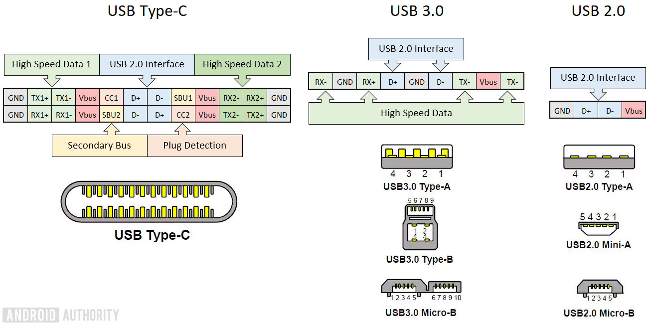
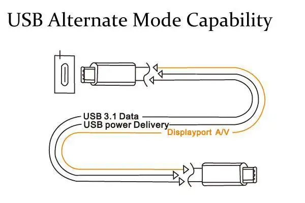
Usb type c otg wiring diagram. Make cable as per schematic in step 4. I made another schematic how you should wire things up so the usb will work as a host or otg mode. Developed at roughly the same time as the usb 31 specification but distinct from it the usb type c specification 10 defines a new small reversible plug connector for usb devices. I havent made it yet though. But usb cable and otg cable look. Typically it utilizes black black red and white cable colours.
The type c plug connects to both hosts and devices replacing various type b and type a connectors and cables with a standard meant to be future proof similar to apple lightning and thunderbolt. All legacy type c cables have only one dd signal pair in the cable so you need a and b. According to usb c wiring diagram there are only four wires used in the cable. With the rapid development of mobile phone industry otg cable gradually sleek into the publics view. In accordance with usb c cable wiring diagram there are just four wires used inside the cable. Black wire serves as ground exactly like in every other device.
The red one is for positive wire with dc ability of 5 liter. Usb cable is a necessary digital accessory in everyday life. Usb device is connected to phone and phone is still charging. Sids e classroom 128045 views. A connect a6 with b6. I would like to create a cable that has a usb a 20 connector on one end and a usb c connector on the other mainly for connecting keyboards to cpus and charging devices.
Diy cable to use otg and simultaneously charge the device windows and android duration. B connect a7 with b7. If you are fitting an old style usb 20 device with new type c connector you need. Also it is the same for micro usb type a and micro usb type b. Actually the extra pin or pin 4 is typically not connected in the normal usb cable but if it is connected to ground pin the phone will turn in a host mode and will be able to read. The pinout diagram for the micro usb type b very similar to usb type a except for the last two pins 4 and 5.
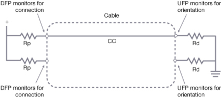
I make usb cables usb a to mini or micro primarily but dont have any experience with usb c. Black cable serves as floor just like in every other apparatus. C connect each cc1 and cc2 to ground with 51k resistor. Typically it utilizes black green white and red wire colours. The pin no1 is 5v acts as a source to the device or source from the device.
Gallery of Usb Type C Otg Wiring Diagram