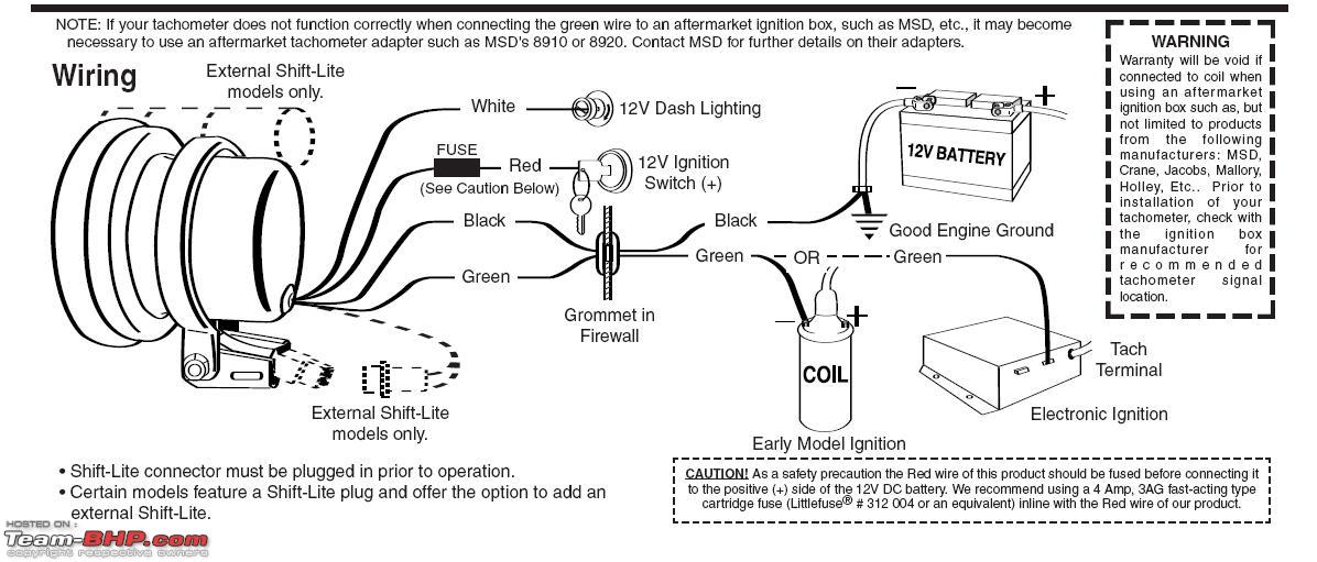
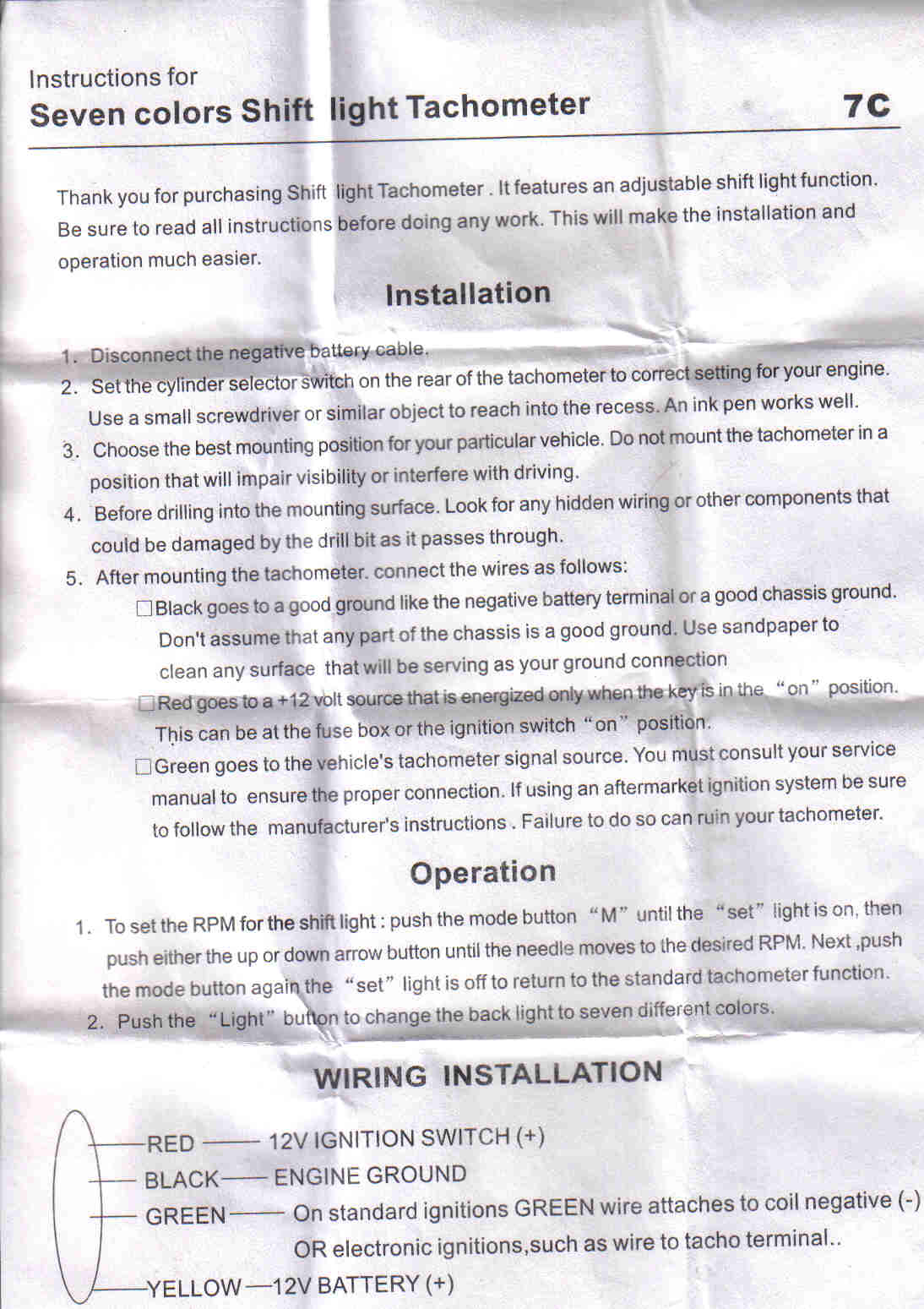
For operation on 4 or 6 cylinder engines a switch adjustment must be made. So i have a red wire a black wire and a green wire these do match the diagrams as the the and the connection to the coil.

Digital Led Rpm Speedometer Tachometer With Hall Senzor
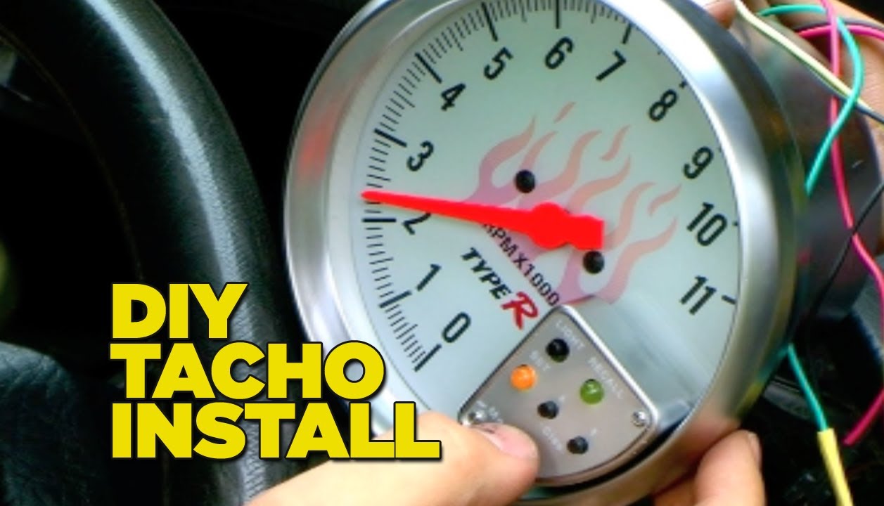
Type r tachometer wiring diagram. It reveals the components of the circuit as simplified shapes and also the power and also signal connections in between the devices. Setup the tachometer to run 2 pulses per rev when connecting it to the engines ecu. Type r monster tacho wiring hi all got myself a type r manster tacho with shift light. Incorrect installation will damage the tachometer. I have a type r tach though mine lacks the recall function. Use plug in connector kit pn 0174732 when installing tachometer only.
It comes with two sets of wiring instructons niether of which actually match the wires i have. Variety of autometer tach wiring diagram. Wire to a junction and attach the wire from pin 4 at this junction ie. A wiring diagram is a streamlined standard pictorial representation of an electrical circuit. The driver plugs into that socket. Connect a wire from pin 5 to a constant 12 or 24 volt source.
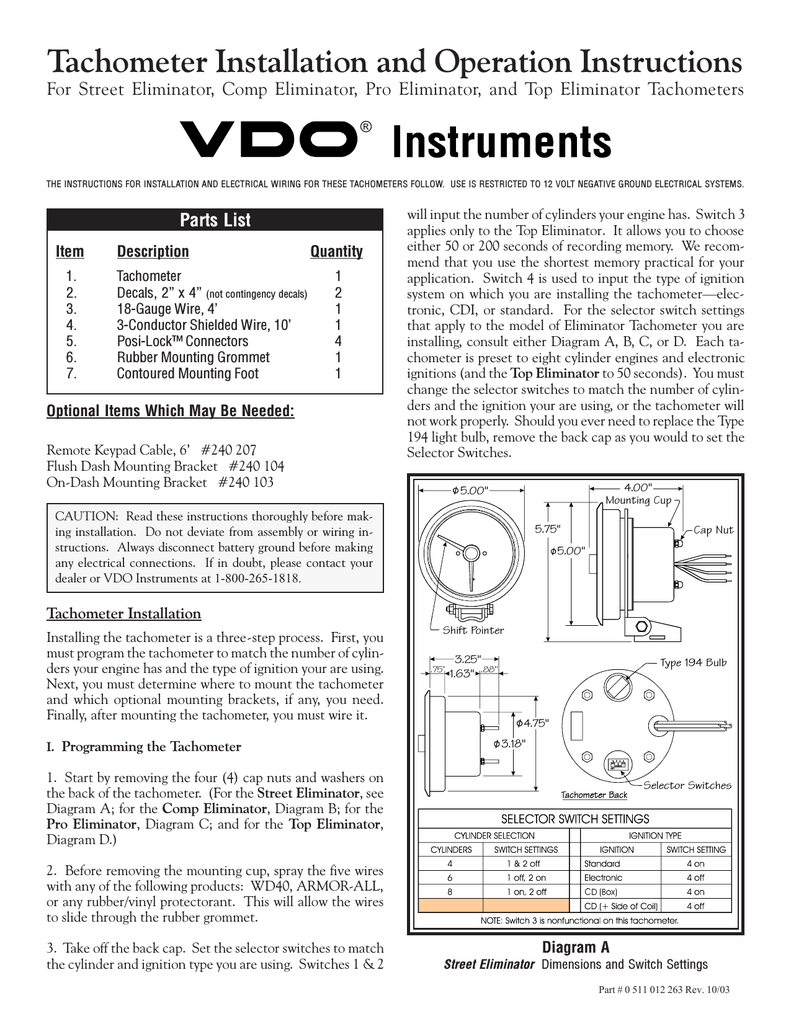
Variety of yamaha outboard tachometer wiring diagram. Use plug infuse block kit pn 0173611 when installing tachometer with other accessories. One such source can always be found where the battery is attached to the metal frame of the vehicle. For chrysler blue gold and silver boxes ford standard electronic ignitions and most other oem standard. It reveals the elements of the circuit as simplified forms as well as the power and signal connections in between the tools. Do you have the el backlight driver connected.
Mine has a pair of redblack wires with a connector at the end. Wire color comments purple use purple signal input if signal is a clean signal tach output terminal ecu tach adapter etc. 2nd 1st switch closed when shifter is in 1st or low only on. This tachometer is factory calibrated for 8 cylinder engines. The yellow wire from our tachometer can receive signal from the ecu by following the diagram in fig 4. The wiring diagram shown is a typical installation.
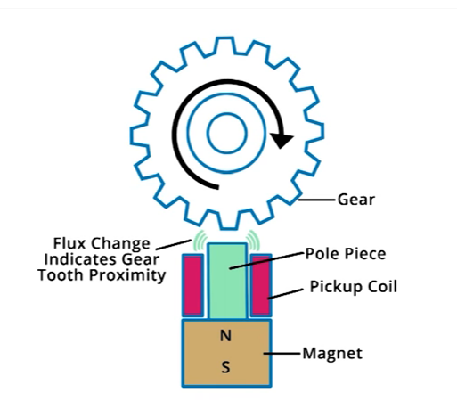
Attach the wire from pin 3 to a ground negative source. 3ag fast acting type cartridge fuse littlefuse 312 004 or an equivalent inline with the red wire of our product for tachs that use a shift lite. Lo w w i r e 1 2 type 4 tach output from ecu some vehicles will have a tachometer output wire coming from the ecu. Use a wiring kit to connect the tachometer to the plug in connector on the remote control or accessory electrical cable. When hooking up the yellow wire. Green use green signal input if you are using a signal from an ignition coil.
For the buttons i can only speculate. Wiring connect the tachometer wires as shown. A wiring diagram is a simplified standard photographic representation of an electric circuit. Refer to diagram d. For tachs without a shift lite we recommend using a 1amp 3 ag fast acting type cartridge fuse littlefuse 312 001 or an equivalent.
Gallery of Type R Tachometer Wiring Diagram