Onoff wiring for afrbup afrxup wht blk afbup s afxup s w 067afbxup s. Belimo characterized control valves technical documentation keywords.
Afb And Afx Series Spring Return Direct Coupled Greenheck
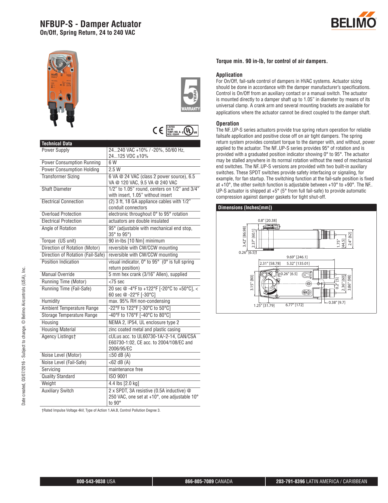
Belimo afbup s wiring diagram. Always read the controller manufacturers installation literature carefully before making any connections. Wht 1 blk 2 wht n blk l line volts a up 1 45 48 neutral load 24 to 240 vac onoff 90 1 4 auxiliary switches afbup s n4 damper actuator technical data sheet nema 4 onoff spring return ac 24240 v 800 543 9038 usa 866 805 7089 canada 203 791 8396 latin america caribbean. By using and further navigating this website you accept this. Transformers belimo actuators require a 24 vac class 2 transformer. If you have any questions contact the controller manufacturer andor belimo. During installation testing servicing and troubleshooting of this product it may be necessary to work with live electrical components.
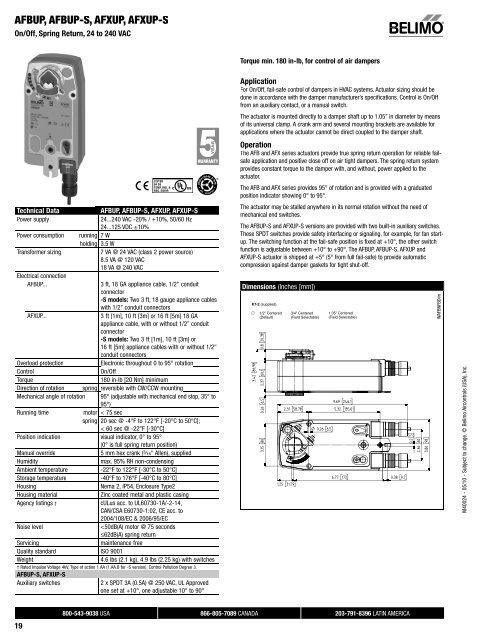
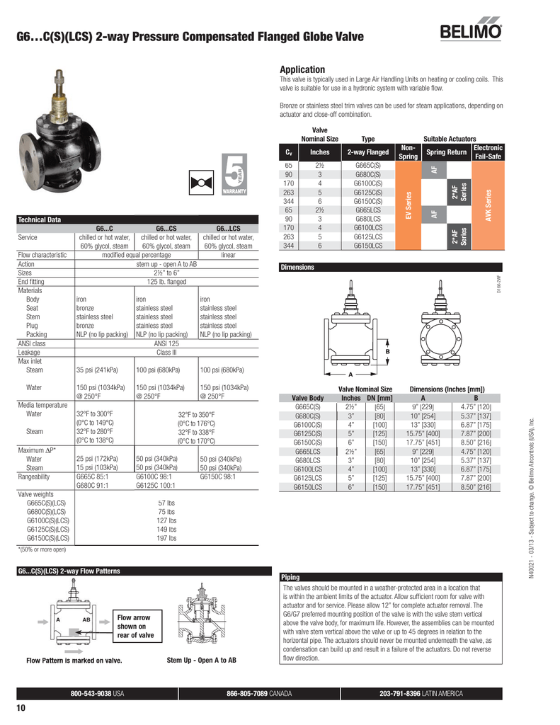
B2 series 2 way. Wht 1 blk 2 wht n blk l line volts a up 1 45 48 neutral load 24 to 240 vac onoff 90 1 4 auxiliary switches afbup s x1 technical data sheet onoff spring return acdc 24 v 800 543 9038 usa 866 805 7089 canada 203 791 8396 latin america caribbean. The afbup afbup s afxup and. B2 series 2 way characterized control valve stainless steel ball and stem afrbup s afrxup s actuators onoff author. The afbup s and afxup s versions are provided with two built in auxiliary switches. 48 parallel wiring required for piggy back applications.
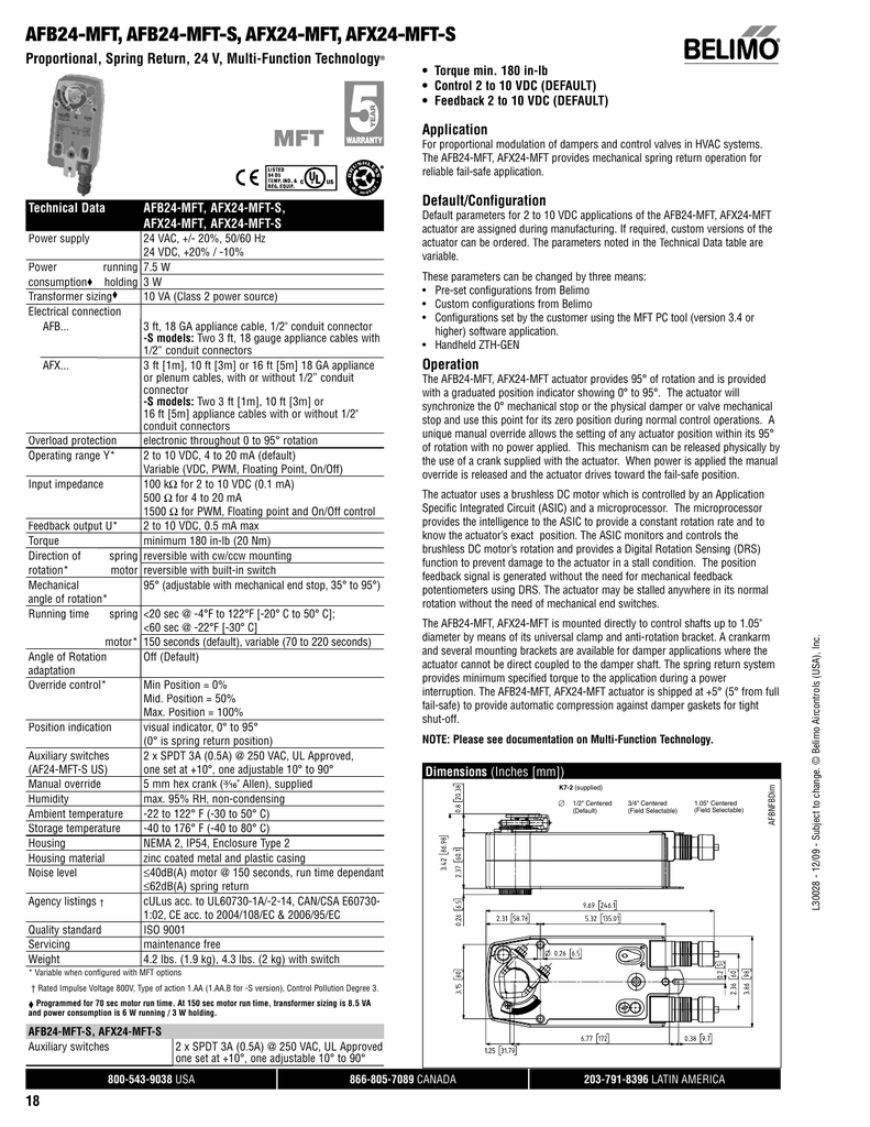
During installation testing servicing and troubleshooting of this product it may be necessary to work with live electrical components. Damper actuator 180 in lb 20 nm spring return ac 24240 v dc 24125 v onoff 2 x spdt. Have a qualified licensed electrician or other individual who has been properly trained in handling live electrical components perform these tasks. 48 parallel wiring required for piggy back applications. Detailed information about the use of cookies on this website is available by clicking here. These spdt switches provide safety interfacing or signaling for example for fan start up.
During installation testing servicing and troubleshooting of this product it may be necessary to work with live electrical components. Follow all instructions in this literature. Wiring diagrams 1 provide overload. This website uses cookies. The switchin g function at the fail safe position is fixed at 10 the other switch function is adjustable between 10 to 90.
Gallery of Belimo Afbup S Wiring Diagram