Usa diagram 10939p000010 customer supplied motor starter contacts l1 l2 l3 l1 l2 l3 v6 u6 w62u v6 u6 w6 2v 2w 1u 1v 1w t5 t8 t9 t7 t1 t2 t3 t6 t4. When the motor is connected the distances to non.

86b1c21 Sew Eurodrive 208 Volt Wiring Diagram Wiring Resources
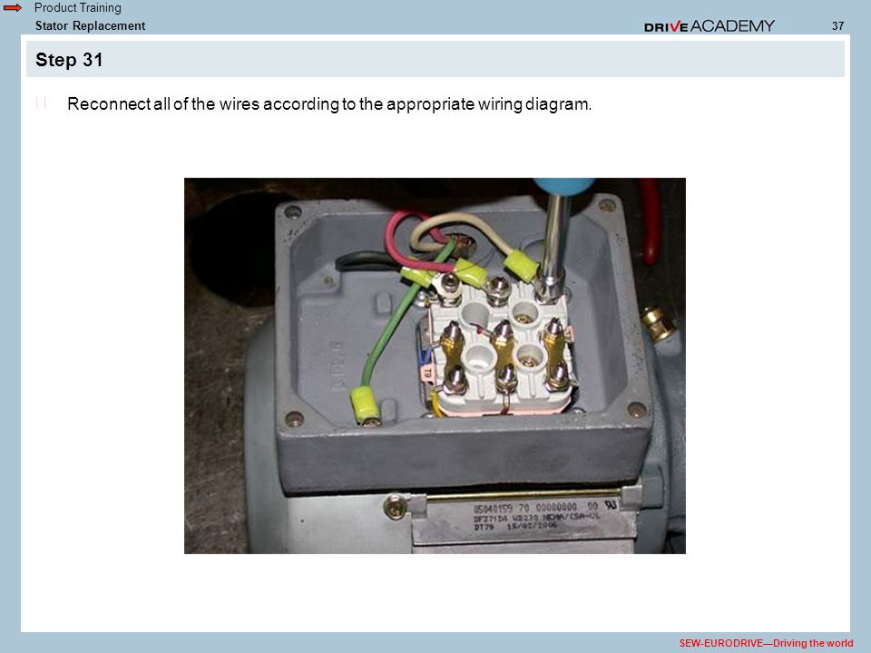
Sew eurodrive motor wiring diagram. A wiring diagram is a simplified standard pictorial representation of an electrical circuit. Dr motor frame size wire length thomas betts ring terminal thomas betts crimp tool dr71 100 8 rb14 8 wt2000. This design is advantageous because it does not require a separate voltage supply and extra wiring for the brake. 2010 dr motor common connection diagrams 3 table of contents. The connection should be a continuous secure electrical connection no protruding wire ends. Use the cable end equipment intended for this purpose.
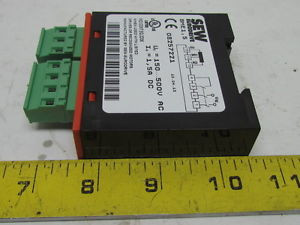
Establish a secure protective earth connection. Observing the wiring diagram. In many wiring diagrams the brake voltage is tapped directly from the motors terminal block. It shows the parts of the circuit as simplified forms and the power as well as signal links in between the devices. The brake releases automatically when power is applied to the motor. Ac motors dr71 225 315 operating instructions.
Back to top. Gear units r7 f7 k7 s7 series spiroplan w operating instructions cm synchronous servomotors. Drive engineering practical implementation. Assortment of sew eurodrive motors wiring diagram. Dr motor common connection diagrams edition 062010 9pd0058 us. Wiring diagrams brake rectifiers and coil data.
Gallery of Sew Eurodrive Motor Wiring Diagram