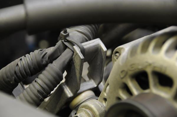
Architectural wiring diagrams act out the approximate locations and interconnections of receptacles lighting and enduring electrical facilities in a building. This problem is caused by a poorly designed metal mount for the harness and requires a thorough inspection of the ficm harness where it passes behind the alternator.
Ba5 2002 Duramax Lb7 Ficm Wiring Diagram Wiring Resources
Lb7 ficm wiring diagram. Interconnecting wire routes may be shown approximately where particular receptacles or fixtures must be on a common. Obtaining from factor a to point b. An initial consider a circuit diagram may be confusing however if you could read a subway map you can check out schematics. I need a wiring diagram for the ficm on my 2002 chevy duramax lb7 answered by a verified chevy mechanic we use cookies to give you the best possible experience on our website. General motors details a chafing problem in the ficm wiring harness tsb 09 06 04 034 as it passes behind the alternator mounted on the front passenger side of the engine. 60 powerstroke ficm wiring diagram a beginner s guide to circuit diagrams.
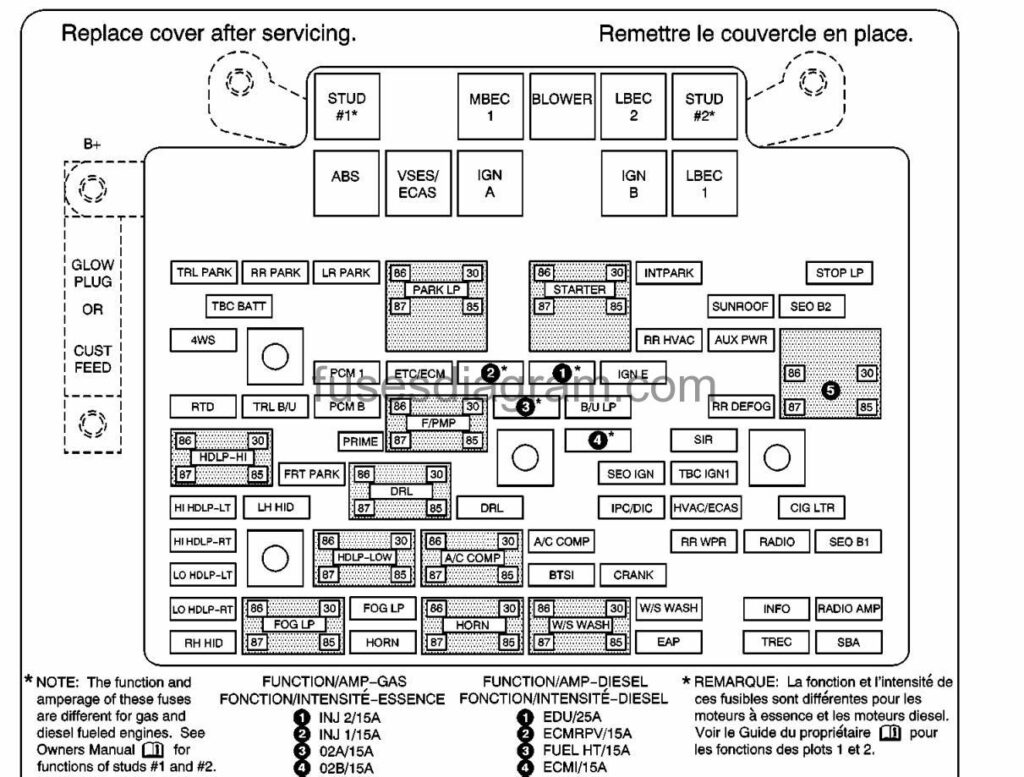
By continuing to use this site you consent to the use of cookies on your device as described in our cookie policy unless you have disabled them. The ficm control relay is the one closest to the engine. Location of the ficm control relay. On 2005 trucks the relay box is large and contains several relays and fuses. On 2003 2004 trucks the relay box is small and contains 2 relays. 2002 duramax lb7 ficm wiring diagram circuit diagram wiring diagram.
Randy johnson1972 18565 views. Ford l diesel ficm repair and operation know your partsficm. How to super flush your cars cooling system duration. 60 powerstroke ficm connector repair must see duration. This is located under the hood in the relay panel located by the drivers side hood hinge. Literally a circuit is the course that enables electrical power to circulation.
7 3 powerstroke ficm location also 6 0 ficm wiring diagram along with icp sensor location 6 0 ford diesel also lb7 engine diagram together with 6 0 powerstroke icp sensor removal as well as ficm wiring diagram furthermore 7 3 idm harness diagram also 7 3l powerstroke engine diagram.
Gallery of Lb7 Ficm Wiring Diagram