Rocker arm and pushrod assembly. Wiring instruction for 70cc 110cc and 125cc with yellow plug.
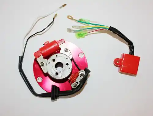
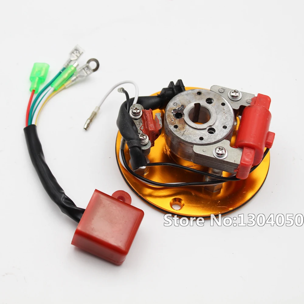
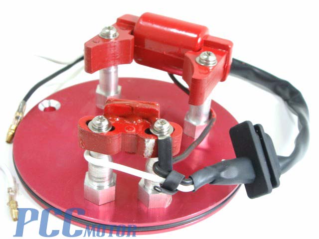
Performance Inner Rotor Kit Magneto Cdi Unit 125cc 140
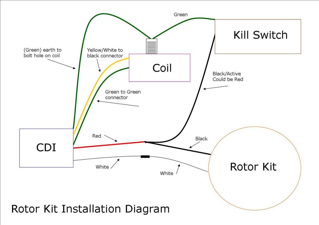
Inner rotor kit wiring diagram. How to remove replace a broken stator. Wiring diagrams for lifan 200cc. Testing electrical systems components. Wires you likely wont need. By using this site you agree to the usage of cookies. Close we use cookies in order to optimise this website and for continuous improvement.
Inner rotor kit pit bike part 3 install wiring. Contains a lower mast support and the necessary hardware to facilitate mounting the ham iv rotator on top of a mast. Inner rotor kit wiring diagram wiring diagram is a simplified conventional pictorial representation of an electrical circuit. Pit bike engine wiring and chassis wiring systems. Rotork wiring diagram selector. Wiring diagrams for lifan 200cc.
Wiring diagrams for 88 110 125 and 140cc engine. Wiring diagram xlh 1970 1971 custom universal basic wiring diagram. Wiring diagram xlch 1970 1971 wiring diagram fxe 1983 1984 solenoid 1966 early 1978 wiring diagram xlh 1972 standard seat. Motoplan mini volano statore stator inner rotor kit test. Honda xrcrf50 70. Pw80 wiring diagrams pw80wd.
3ø wiring diagrams 1ø wiring diagrams diagram er9 m 3 1 5 9 3 7 11 low speed high speed u1 v1 w1 w2 u2 v2 tk tk thermal overloads two speed stardelta motor switch m 3 0 10v 20v 415v ac 4 20ma outp uts diagram ic2 m 1 240v ac 0 10v outp ut diagram ic3 m 1 0 10v 4 20ma 240v ac outp uts these diagrams are current at the time of publication. The lower mast support kit p n 51467 10. China inner rotor wiring. 2 cycle engine trouble shooting guide. Wiring diagram flhs 1980 1981 prestolite starter motor. 14 hammer court hoppers crossing victoria 3029 australia monday friday 9am 5pm.
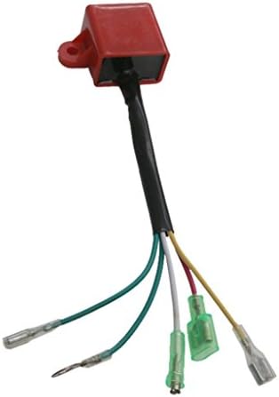
155cc or 155z wiring. 80cc bicycle engine instruction. For further information please refer to our privacy policyprivacy policy. Pitbike rectifierregulator wiring diagram. When using the lower mast support antenna size is restricted to 75 square feet of wind surface area. Japan inner rotor kit.
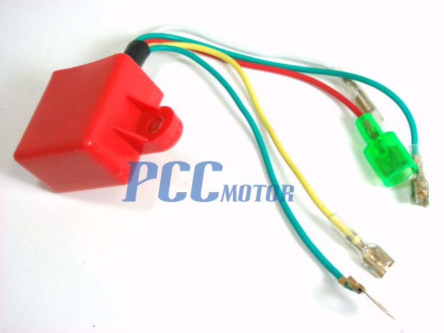
It shows the components of the circuit as simplified shapes and the skill and signal friends with the devices. Lifan and zs outer rotor wiring. Inner rotor kit wiring the workshop. So what id do is measure the voltage from the main coil black wire multimeter positive on that and negative on the frame on idle its normally 35volts ac. Common pit bike cdi box identification. The rotator unit must be wi red to the controlunit with an 8 wire cable.
Isaac p 81300 views.
Gallery of Inner Rotor Kit Wiring Diagram