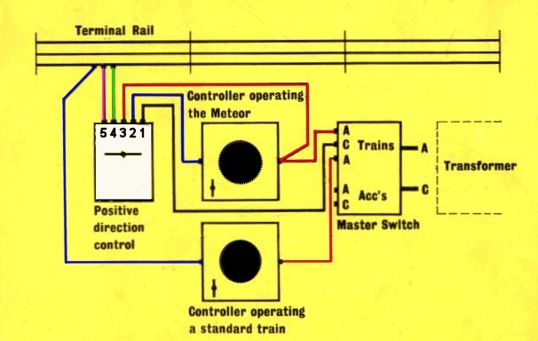
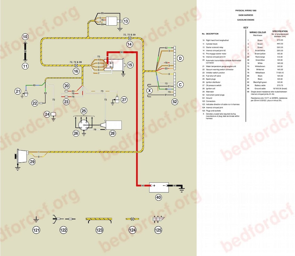
Here is an important notice. The trailer wiring diagram above give one flavor for routing direction starting at the tongue connector then wrapping around the trailer.
Van Truck Seller Innolift Stacker 500kgs Self Lift Manual
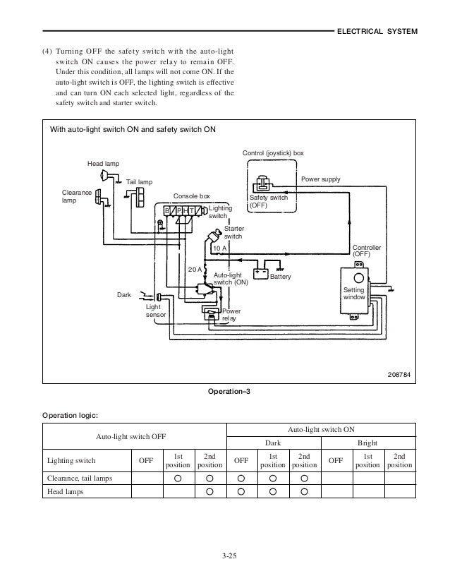
Tail lift wiring diagram. Shown in diagram if necessary. And electric diagrams standard lifts dhollandia tail lifts a complete range of tail lifts 7 main objectives implement the choice between the lift circuit and tilt circuit analyse and understand the working principle s of the standard lift the most popular in the product range. 7 define the differences in electrical wiring and hydraulic circuits. Installation manual column tail lifts 14. Drill a 12mm diameter hole in a suitable place in the dashboard to mount the in cab isolation switch. Since 1957 when max lugash invented the first tuk a way lift weve been driven by innovation.
3place the mounting brackets on the underbody tube near their final position. Identification and classification of the tail lifts. Position the lift close to the vehicle rear and raise the lift until the top of the lift housing is level with the vehicle floor using a forklift truck or other suitable lifting device. Connect the isolation switch following the wiring diagram. Raise underbody tube to its approximate final position and attach the lift arms to the platform with the pins provided. The tail lift is fitted to a vehicle and the fitting complies with the conditions of the ce directives with the fitting instructions of dhollandia and the fitting and body build ing instructions of the vehicle manufacturer.
As officially appointed parts distributors for the uks tail lift shutter for bulk order enquiries for dhollandia tail lift parts please call us on operate the tail lift safely and continue to keep it in good. Please choose a year from the menu at left to start your search. Connect the power cables to the vehicle battery. 2place the platform on the rear of the vehicle center the platform and securely clamp it top and bottom. Welcome to winnebago industries wiring diagrams. 7 electrical hydraulic wiring diagrams b29.
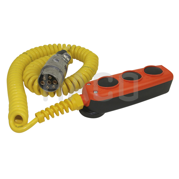
Either approach is fine. Control box and a 2 push button control box see diagram. Remove the toe guard. You can find help on the following items directly here. A leading suite of products. Corporate over 60 years of leadership discover the maxon advantage.
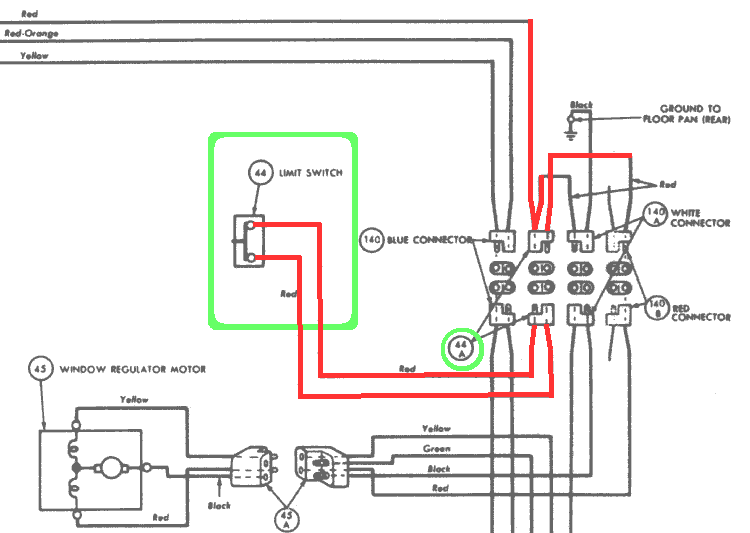
Ensure the body rear is flat and clear before fitting the lift and the vehicle battery is disconnected. Ensure that the in line fuse is locat. Other people suggest splitting the wires near the tongue then routing down both sides right and left specific. They can be found right next to the circuit board in the main tube. There is an electrical connection and hydraulic diagram for the respective model of tail lift included with all palfinger tail lifts.
Gallery of Tail Lift Wiring Diagram