The flow portion of the. The jandy aqualink rs is a multi function pool controller that can fully control the.
25705c1 1977 Buick Electra Wiring Diagram Wiring Resources
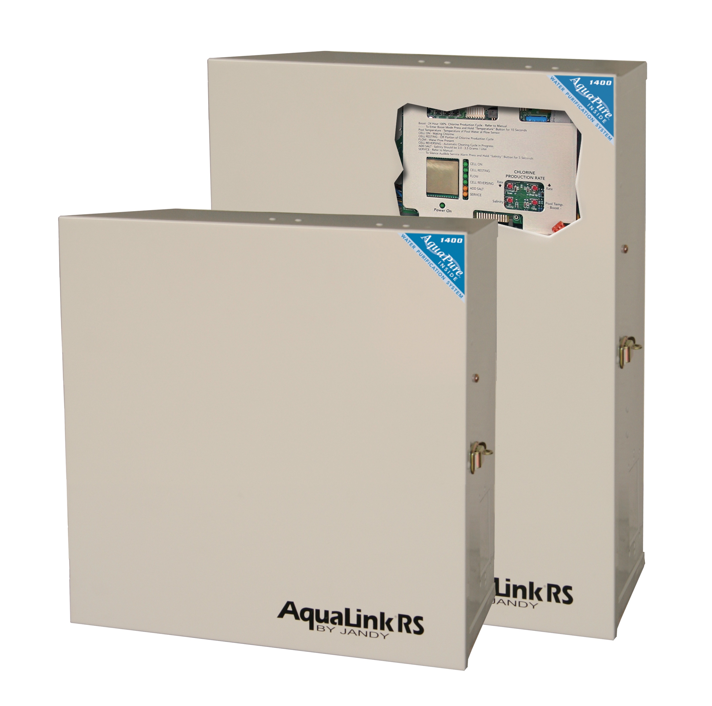
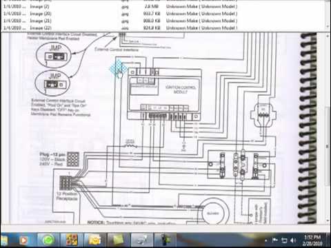
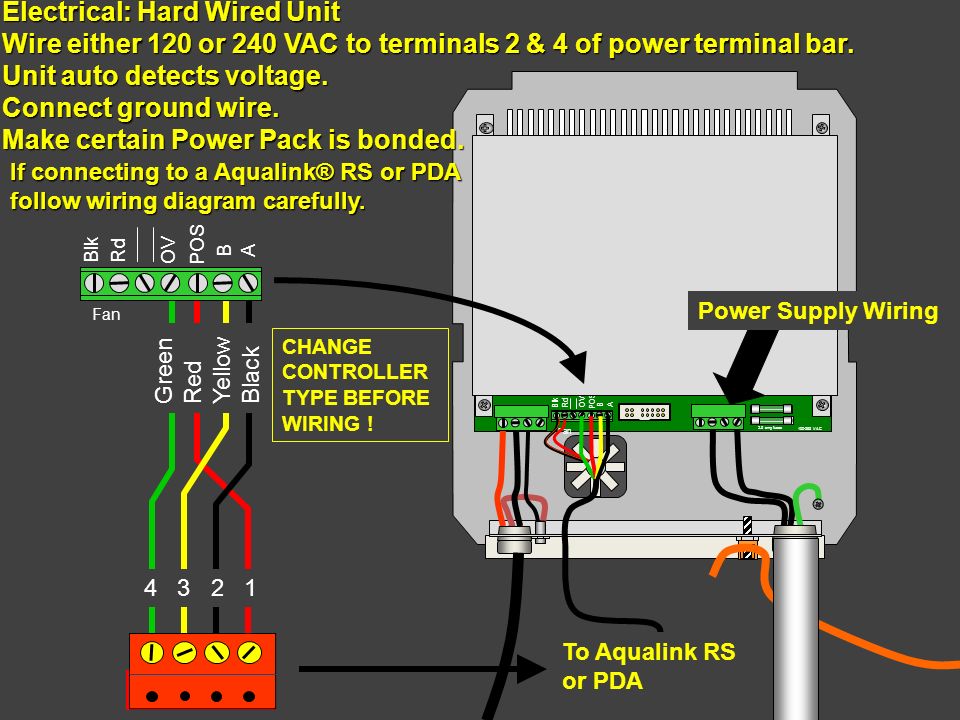
Jandy aqualink rs wiring diagram. If either of the communication wires inner pair is broken or misconnected but the power supply wires the outer pair are connected properly the controller will stop responding. Premium automation at its finest jandy aqualink rs systems enable total control of your backyard experience. Note when connecting to the aqualink rs plug the jvas into the intake return and cleaner jva sockets. Power center the aqualink rs purelink power center converts ac electrical current to a low voltage dc current which is required by the cell to perform the electrolysis. Plug in the red terminal bar and hang the controller on the back of the housing then go to the power centerjandy aqualink wiring diagram wiring libraryjandy aqualink rs installation manual pdf download. Slide dip switch s1 6 to the on position.
View and download jandy aqualink rs installation manual online. The jandy pool and spa lights are intended for installation in fresh water and non fresh. Aqualink rs systems are fully integratabl. All button and onetouch control panels. Vac wiring diagram for the aqualink rs purelinktm system. Aqualink rs control panel pdf manual download.
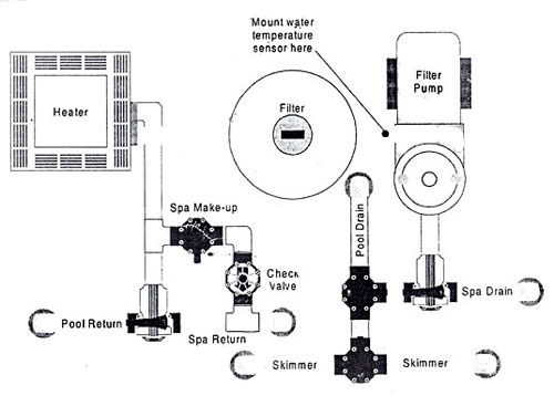
All button and onetouch control systems poolspa combination systems and poolspa only systems. Aqualink rs control panel pdf manual download. Aqualink rs6 aqualink rs series aqualink rs8 aqualink rs onetouch. Aqualink rs series aqualink rs8 aqualink rs onetouch. View and download jandy aqualink rs installation manual online. Shared heater check valves 4 spa intake spa filter spa return spa pump pool intake pool pump pool filter pool return jva jva jva to solar if installed.
Page 34 power center wiring diagram r e tu rn s o la r e le c t. Aqualink rs pool spa automation system. It may show a steady screen of information and stop responding to its buttons. See wiring diagram in section 4 figure 5. Wiring diagram for aqualink rs dual equipment rs26 o ptio na l r ela y s ys te m p ow e r g ro un din g b ar w ire n ut to 1 20 va c p o w e r wiring diagram for aqualink rs dual equipment rs26 210 214. The power center is connected with the pool circulation pump electrical source so that the electrolytic cell only operates when the pool pump is on.
J v a j v a h e a te r in ta k e c le ane r s o lar j v a p. Jandy aqualink rs wiring diagram follow the wiring diagram in the aqualink rs installation manual for connections. Wiring to an aqualink rs control system9. Communicate via serial communication using signals like the standard rs 485.
Gallery of Jandy Aqualink Rs Wiring Diagram