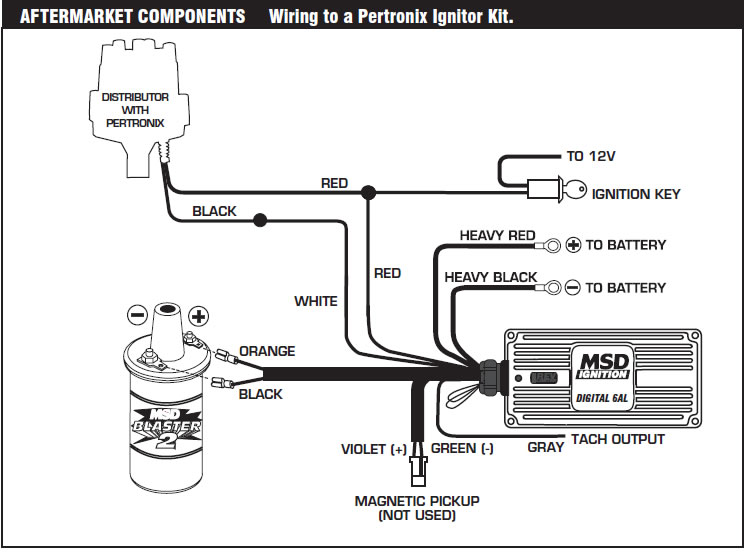
A wiring diagram is a streamlined standard photographic depiction of an electric circuit. These instructions will probably be easy to understand and implement.

Ford Dura Spark Ford Tfi Actron Cp9087 User Manual Page
Ford tfi module wiring diagram. It is about one inch wide and about four inches long. Tfi iv ignition system wiring diagram courtesy of ford motor co. Variety of ford tfi wiring diagram. Wiring diagram comes with several easy to follow wiring diagram instructions. Installing the ford tfi system. It shows the elements of the circuit as simplified forms and the power and signal links in between the devices.
Ford tfi ignition wiring diagram wiring library ford ignition control module wiring diagram. Youll also notice a large grey clip on harness attached to it. 4 disconnect the wire at the s terminal of the starter relay and attach remote starter switch. A very first look at a circuit representation could be complicated yet if you could check out a subway map you can read schematics. 2 disconnect the harness connector from the tfi module and connect the tfi tester. Its intended to help all of the common consumer in creating a proper program.
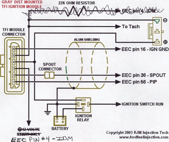
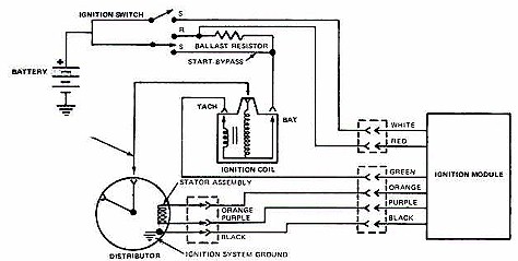
The tfi iv system module is mounted on the distributor base it has 6 pins and uses an e core ignition coil named after the shape of the laminations making up the core. See the trouble shooting basic procedures article in the general trouble shooting section. Ford tfi module wiring diagram wiring diagram is a simplified enjoyable pictorial representation of an electrical circuit. Testing preliminary steps 1 visually inspect engine compartment to ensure that all vacuum hoses and spark plug wires are properly routed and securely connected. The tfi modules are available as holley 891 105 or accel 35368 46 as well as from a number of aftermarket sources. A wiring diagram usually gives information about the relative outlook and understanding of devices and terminals upon the devices to back up in building or servicing the device.
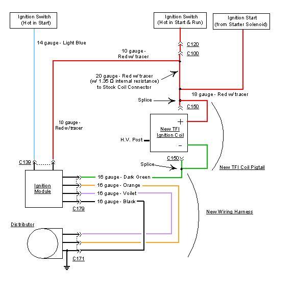
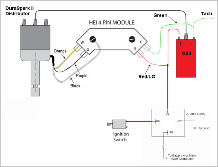
From here there are 2 ways you can wire up the remote tfi. Fabricate the wiring harness using 3 lengths of at least 18 gauge wire. The tfi iv module supplies voltage to the profile ignition pick up pip sensor which sends the crankshaft position information to the tfi iv module. The spade connectors are your standard 18ga connectors. 3 connect the red lead from the tester to the positive side of the battery. Ford tfi wiring diagram a beginner s overview of circuit diagrams.
The tfi module is a gray box fitted to the side of the distributor. Tfi module wiring diagram to 94 f350 everything you ever wanted to know about your ford mustangs tfi module including way up until the model actual usage in mustangs was from so 10 years. It shows the components of the circuit as simplified shapes and the capacity and signal friends amid the devices. The distributor itself uses a hall effect sensor. Wiring method 1 new harness with connectors on both ends.
Gallery of Ford Tfi Module Wiring Diagram