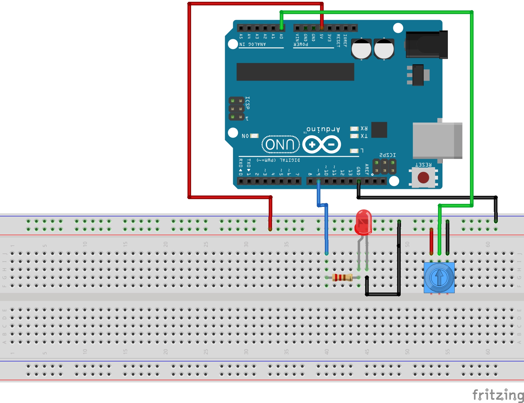
The led will lit up also with values up to 1k ohm. Then it wouldnt matter if.
Arduino Rgb Led Tutorial Arduino Project Hub
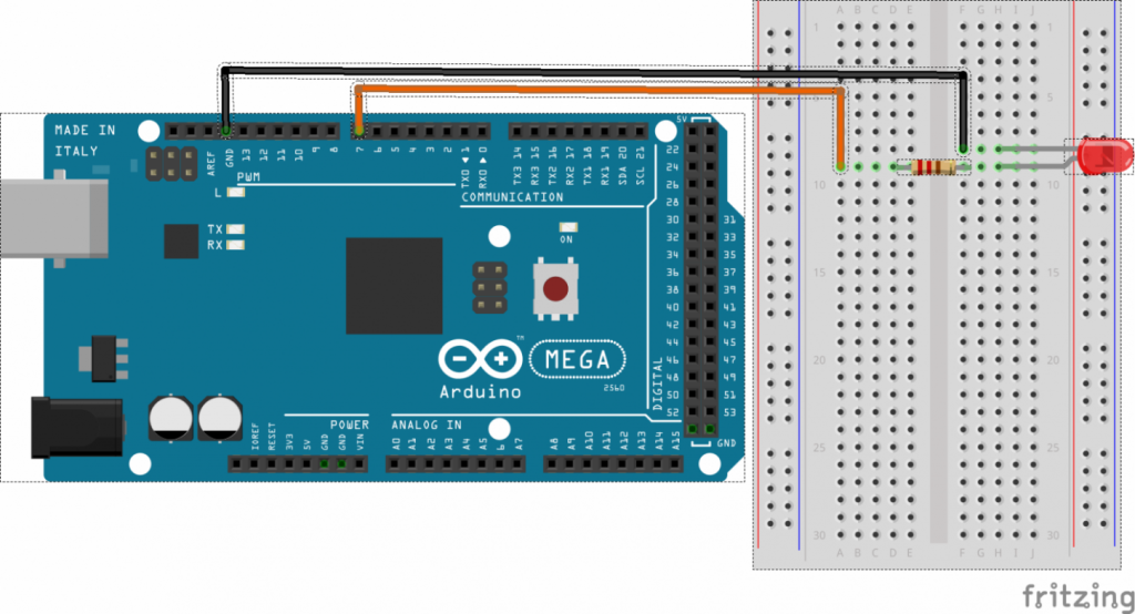
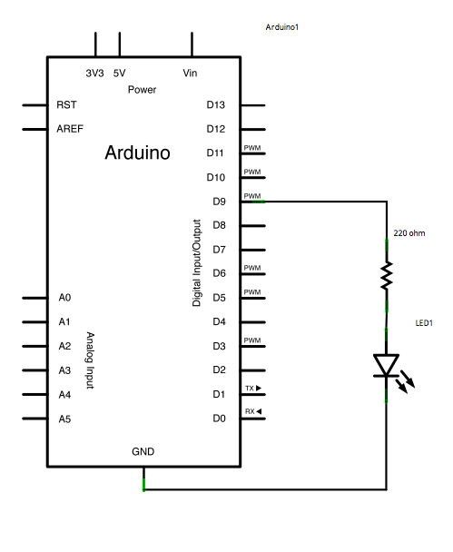
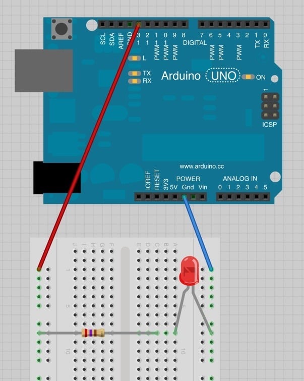
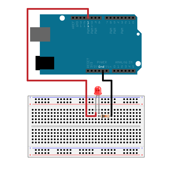
Arduino led wiring diagram. The pin the led is connected to void setup pinmode led output declare the led as an output void loop digitalwrite led high turn the led on delay 1000 wait for 1000 milliseconds 1 second digitalwrite led low turn the led off. Run one wire red to the 5v socket on the arduino. Put your arduino nano on the breadboard. The value of the resistor in series with the led may be of a different value than 220 ohm. Connect the short leg of the led the negative leg called the cathode to the gnd. Seamless circuit design for your project.
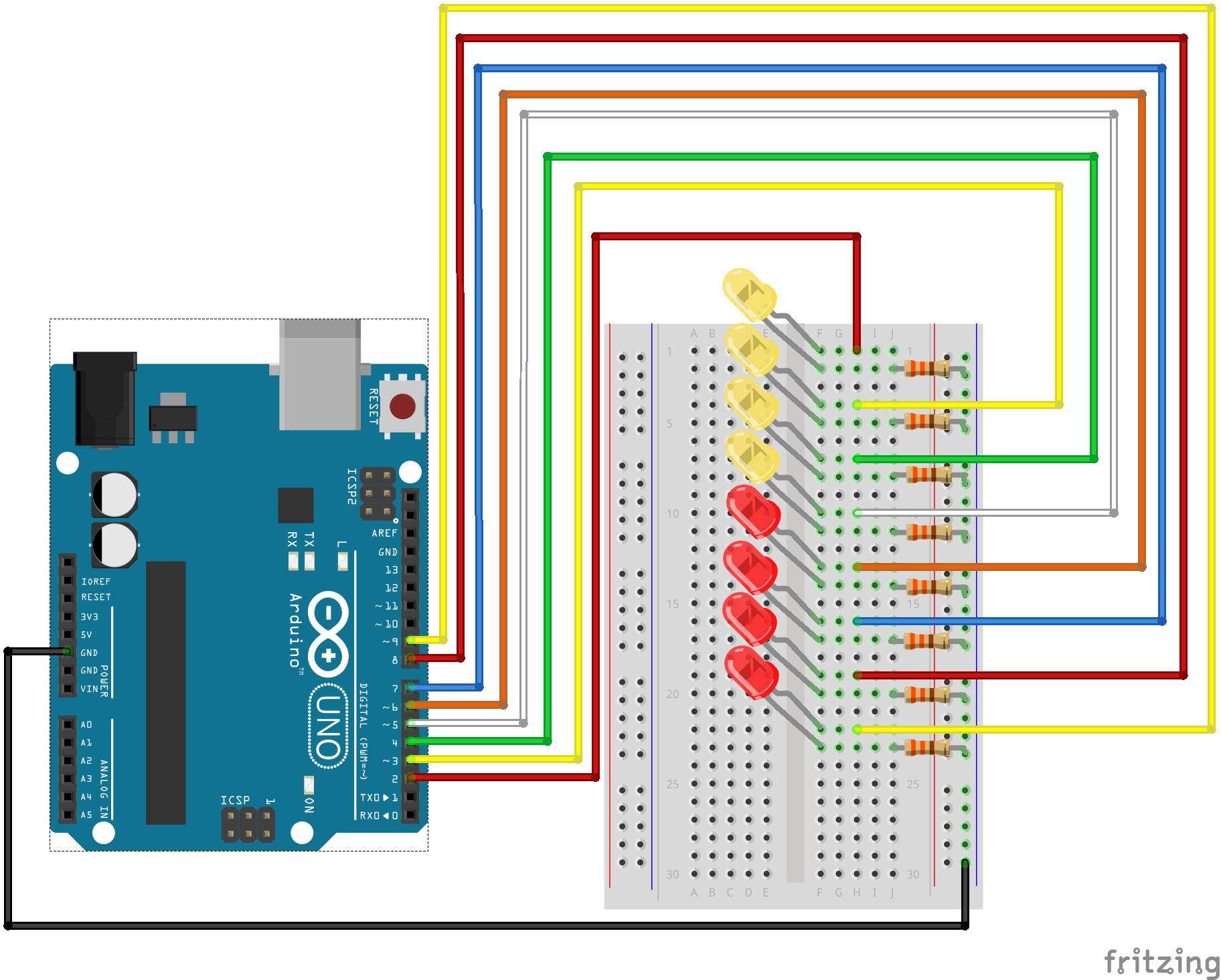
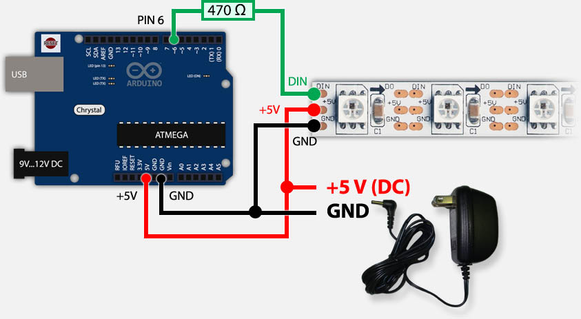
The word led stands for light emitting diode. Wiring leds in parallel allows many leds to share just one low voltage power supply. In the diagram below we show an uno board that has d13 as the ledbuiltin value. This led strip is made by ws2812b leds wired in series. Conecta la resistencia entre el pin digital 2 de arduino y el positivo del led. That same leg of the button connects through a pull down resistor here 10k ohm to ground.
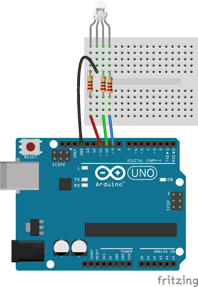
Led blink codearduino copy and paste this code into your arduino ide or web editor int led 13. The led is an rgb led and works like so. This means that you can control lots of leds using just one digital pin of your arduino. In the following figure you can see the chip inside the led. Conecta el pin gnd al negativo del led. But a better way is to draw a wiring diagram.
Circuitoio is an online tool for designing electronic circuits. Select your component combination and instantly get a detailed list of parts a step by step wiring guide and custom test code for your circuit. The sketch and heres the new sketch slightly modified from the sample in the arduino ide which you can load by going to file examples 01basics fade or you can get this sketch from github. We could take those same four 3v leds and wire them in parallel to a smaller power supply say two aa batteries putting out a total of 3v and each of the leds would get the 3v they need. Weve used the led to make a blinking light in lessons 1 and 2. Arduino lcd wiring diagram.
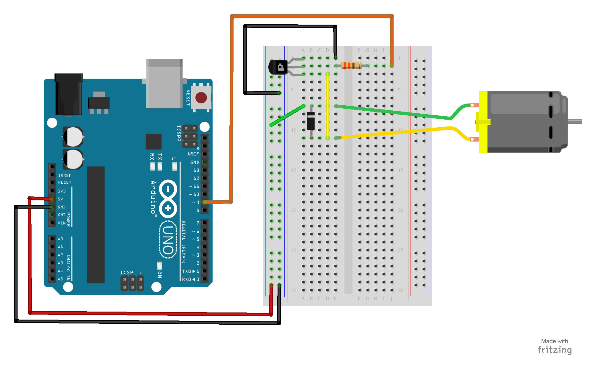
The third wire goes from digital pin 2 to one leg of the pushbutton. Wire the resistor between the arduino digital pin 2 and the positive of the led. Youll need to use wires to reach the arduino. In short wiring in series divides the total power supply between the leds. Connect three wires to the board. This allows a communication via a one wire interface.
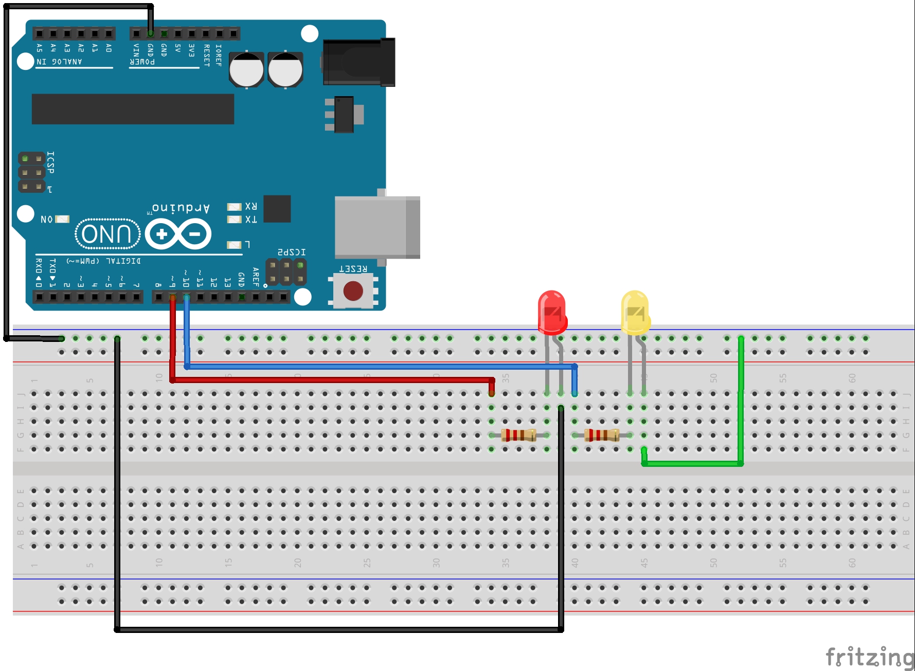
The light emitting part well that makes sense. These leds have an ic built right into the led. Wire the gnd pin to the negative of the led coloca el arduino nano en la protoboard. The wiring diagram for the blinking led experiment. The first two red and black connect to the two long vertical rows on the side of the breadboard to provide access to the 5 volt supply and ground. Thanks to the magic of fritzing one of my favorite tools for drawing wiring diagrams you can see my wiring schematic.
Gallery of Arduino Led Wiring Diagram