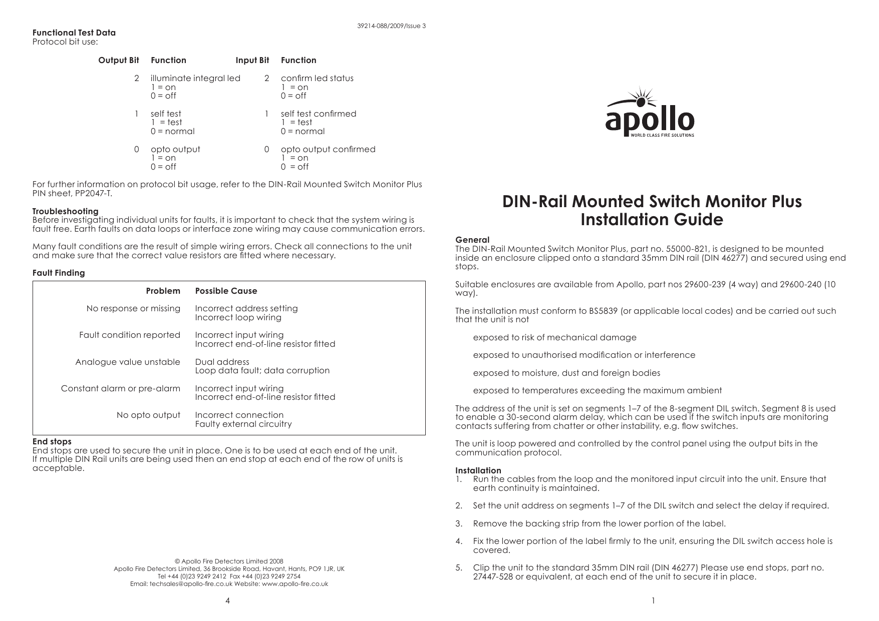
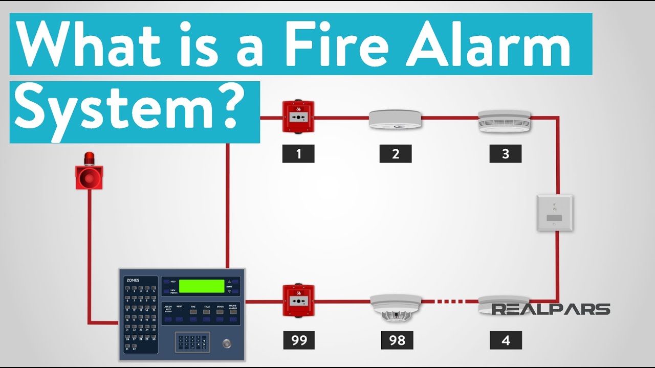
Zone r l1 l2 r l1 l2 optional remote led xp95 loop p f kfd0 barrier view from top protocol translator view from top any loading resistor should be connected between l1 and l2 of the first base 7 8 9 10 11 12. Using the apollo xp95 interface size.

Xp95 Engineering Product Guide Pdf Document
Apollo xp95 interface wiring diagram. Field interface xp95 new mini sm size. Declaration of performance size. Contact us eu fire security ltd. Audio visual. Detail of wiring diagram for xp95 is. Xp95 series security sensors pdf manual download.
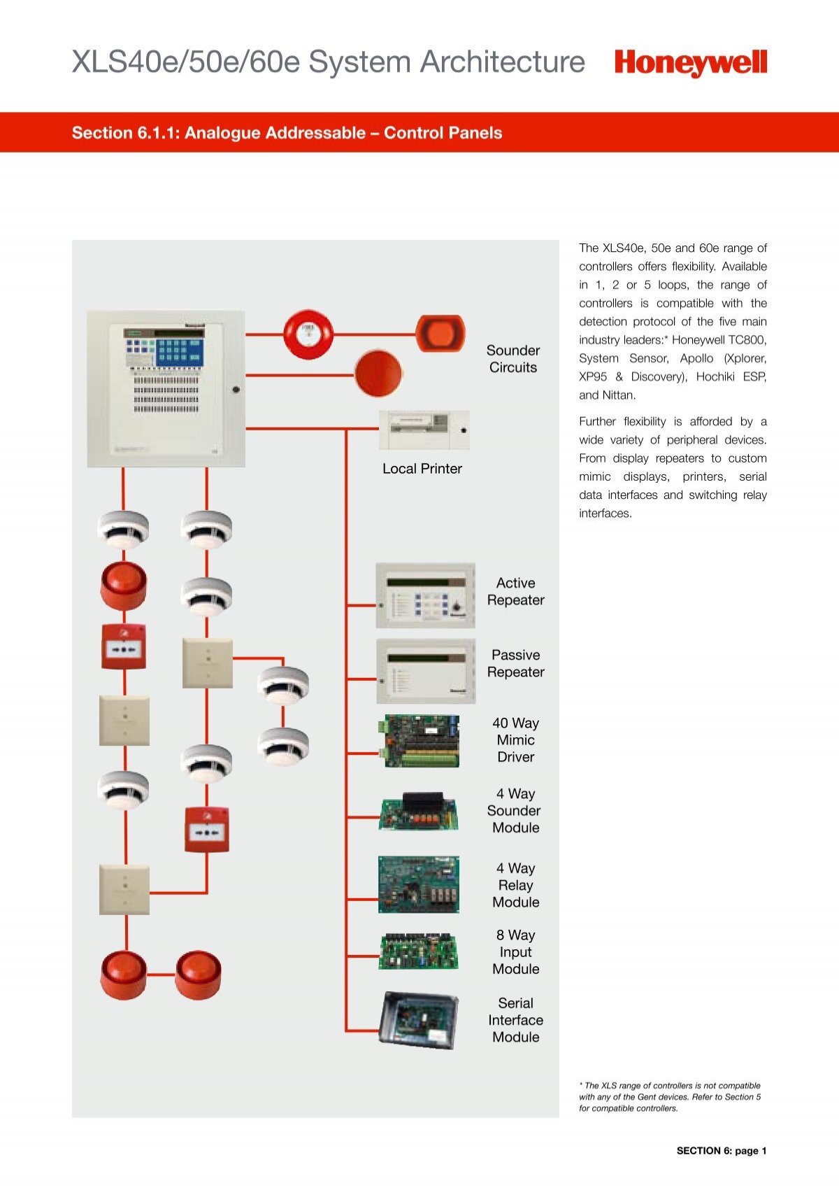
It is suitable for medium to large applications with simple installation requirements. Xp95 isolating base xp95 base terminal block connections xp95 isolating base terminal functions l1 not used context plus analogue addressable dil switch xp95 detectors. Safety barrier xp95 is. Msapolloapolloaddressablexp95xp95positiveswitchingisolatorig102pdf connect the wiring following the diagram overleaf. Xp95 the xp95 range of analogue addressable fire detectors uses tried and trusted technology to give the best performance and has unique features that benefit the installer and the end user. Detector high integrity wiring figure 3.
Sounder beacons vids. Adi 2021 din rail interface enclosure 10 interfaces. Xp95 din rail mains switching inputoutput unit. Apollo xp95 interfaces. Wiring multiple beams on a zone size. Adi 2020 din rail interface enclosure 4 interfaces.
Fire beam adjustable bracket instructions size. Connection to fike twinflex panel size. View and download apollo xp95 series manual online.
Gallery of Apollo Xp95 Interface Wiring Diagram