All wiring must conform to applicable local codes ordinances and regulations. Variety of notifier fcm 1 wiring diagram.

Notifier Fcm 1 Supervised Control Module Switch Relay
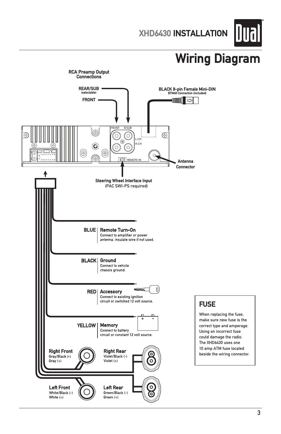
Notifier fdm 1 wiring diagram. Surface mounted electrical boxes smb500 are avail able from notifier. It reveals the parts of the circuit as streamlined forms and the power as well as signal links in between the tools. Install module wiring in accordance with the job drawings and appropriate wiring diagrams. A wiring diagram is a simplified conventional pictorial representation of an electric circuit. The box must have a minimum depth of 218. This module is intended for power limited wiring only.
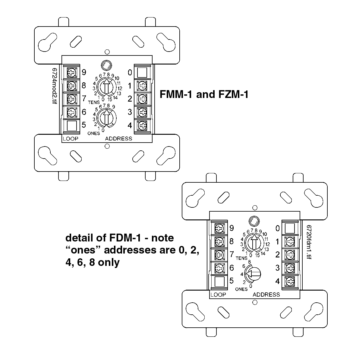
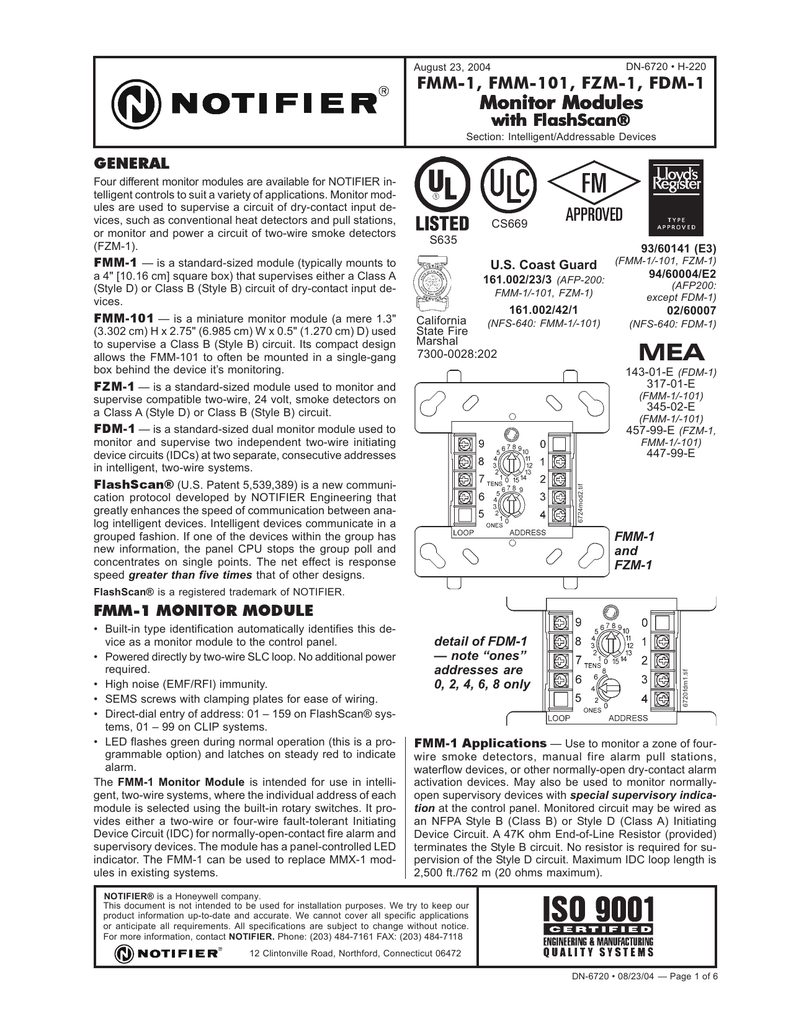
All wiring must conform to applicable local codes or dinances and regulations. Address 56 then it will automatically assign itself to ad dresses 56. Connecting a releasing device to the fcm 1 rel. Mounting the fzm 1 mounts directly to 4 square electrical boxes see figure 2a. 16112018 16112018 3 comments on notifier fcm 1 wiring diagram. Monitor modules model numbers include the fmm 1 fmm 101 fzm 1 and fdm 1.
Trical boxes smb500 are available from notifier. Notifier fcm 1 wiring diagram. Compatible notifier system control panel list available from noti fier. All wiring must conform to applicable local codes ordi. Install module wiring in accordance with the job draw ings and appropriate wiring diagrams. Compatible notifier system control panels only list available from notifier.
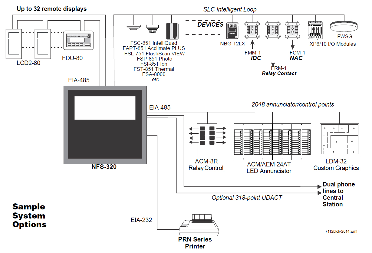
Notifier nfs manual online. Set the address on the module per job drawings. To a compatible notifier system control panel only list available from notifier. The box must have a minimum depth of 218. For example if the fdm 1 is set to able from notifier. Notifiers offers a variety of intelligent monitor modules for diverse applications.
All wiring must conform to applicable local codes. Surface mounted electrical boxes smb500 are available from notifier wiring note. 412 h x 4 w x 114 d mounts to a 4 square by 218 deep box accessories. Wiring diagrams wiring diagrams the following wiring diagrams are included. Install module wiring in accordance with the job drawings and appropriate wiring diagrams figures 3 4. Fdm 1 typical dual two wire style b initiating device circuit configuration.
Mounting the fcm 1 mounts directly to 4 square electrical boxes see figure 2a. Summary of contents for notifier fdm 1 page 1 compatibility requirements a78 2318 13 to ensure proper operation this module shall be connected to a figure 2a. Connecting a releasing device to a fcm 1 module connecting an. Monitor modules supervise a circuit of dry contact input devices such as conventional heat detectors and pull stations or monitor and power a circuit of two wire smoke detectors. This module is intend ed for power limited wiring only. Surface mounted electrical boxes smb500 are available.
Releasing applications c limited energy cable cannot be used to wire a. Notifier nfse manual online.
Gallery of Notifier Fdm 1 Wiring Diagram