The red wire is for the ignition switch. Volvo penta wiring diagram gsi.

Caerbont Tachometer Wiring
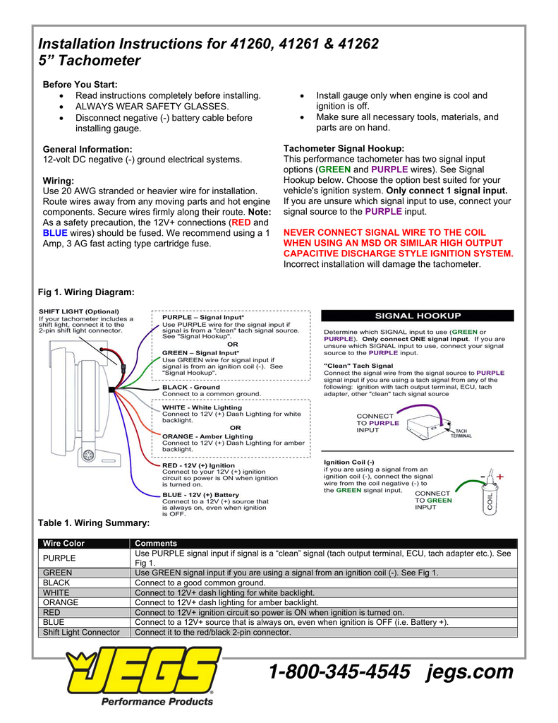
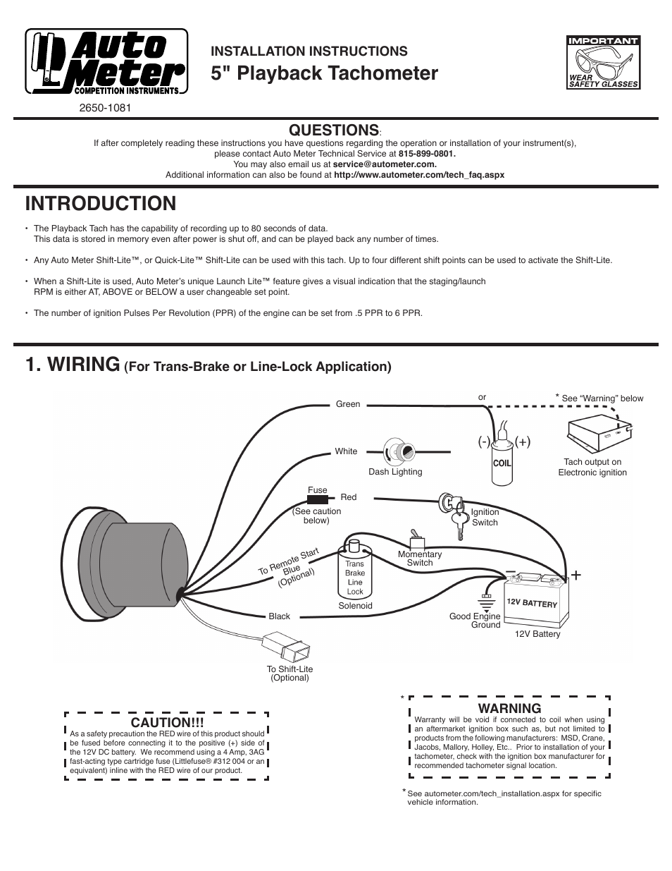
Tacho wiring diagram. We recommend using a 4 amp 3ag fast acting type cartridge fuse littlefuse 312 004 or an equivalent inline with the red wire of our product for tachs that use a shift lite. Connect the wire from pin 4 to a switched 12 volt or 24 volt source. Volvo penta gi e wiring diagram for engine and instrument panel. Connect the white wire to the inside lighting switch which will illuminate the tachometer when the headlights are on. Volvo wiring diagram add on. Variety of autometer tach wiring diagram.
Tacho sensing wire is connected to transistor emitter and transistor collector is connected to positive battery or ignition key. Refer to diagram d. Tacho sensor seems to be an inductive one and operates off the fuel pump drive gear. Mine was salvaged from my old truck 3m quick splice connectors 14 18 gauge 410 walmart tools. Tachometer can be purchased from most any auto parts store for as low as 33. A wiring diagram is a simplified standard photographic representation of an electric circuit.
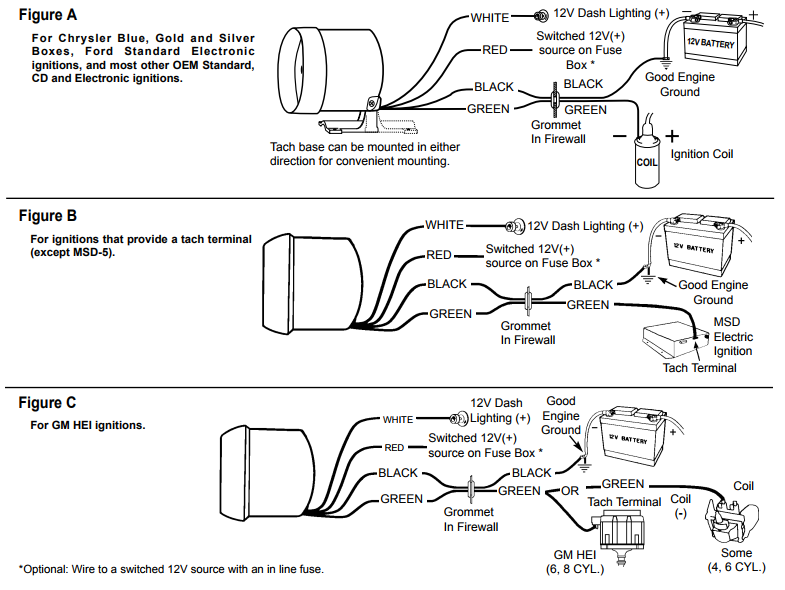
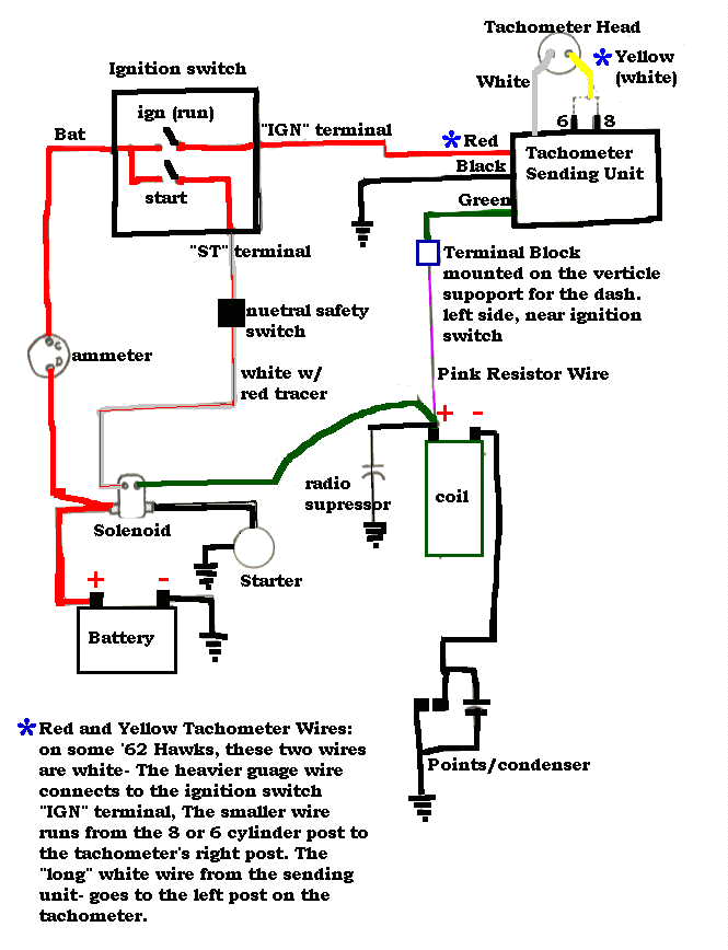
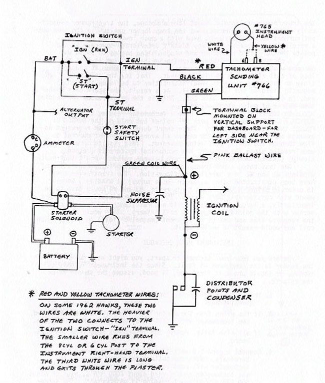
Connect the green wire to the negative post of an existing electronic coil or electronic ignition system using a tachometer adapter as a connector. In my case i first started with the figure a wiring but later figure b with the installation of the hei distributor in my jeep. For tachs without a shift. Wiring volvo penta diesel panel need help. It reveals the elements of the circuit as simplified forms as well as the power and signal connections in between the tools. Volvo penta gi cable wiring diagram.
A wiring diagram is a streamlined standard pictorial representation of an electrical circuit. This article on how to wire an electronic tachometer doesnt have anything to do with project x other than that 57 is the granddaddy to super chevys chevelle. Wire cutters wire strippers automotive diagnostic tool used for finding tachometer wire ratchet and sockets screwdriver drill. Connect a wire from pin 5 to a constant 12 or 24 volt source. A switched 12 or 24 volt wire can be found coming from the ignition switch. Wiring the tachometer connect the tachometer wires as shown in the wiring diagrams below which are typical installations.
As a safety precaution the red wire of this product should be fused before connecting it to the positive side of switched power source. The transistor is working like a relay switch to supply current for tacho to sense engine speed and that relay switch is controlled by coil or igniter. Follow this wire to a junction and attach the wire from pin 4 at this junction ie. Variety of yamaha outboard tachometer wiring diagram. It reveals the components of the circuit as simplified shapes and also the power and also signal connections in between the devices.
Gallery of Tacho Wiring Diagram