Alternator basics tips tricks 1 wire models of gm ford mopar from 1960 1980s autorestomod episo duration. Ford alternator wiring diagram internal regulator.
Af5 Rectifier Wiring Diagram With Alternator Wiring Library
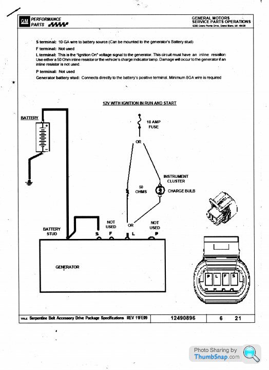
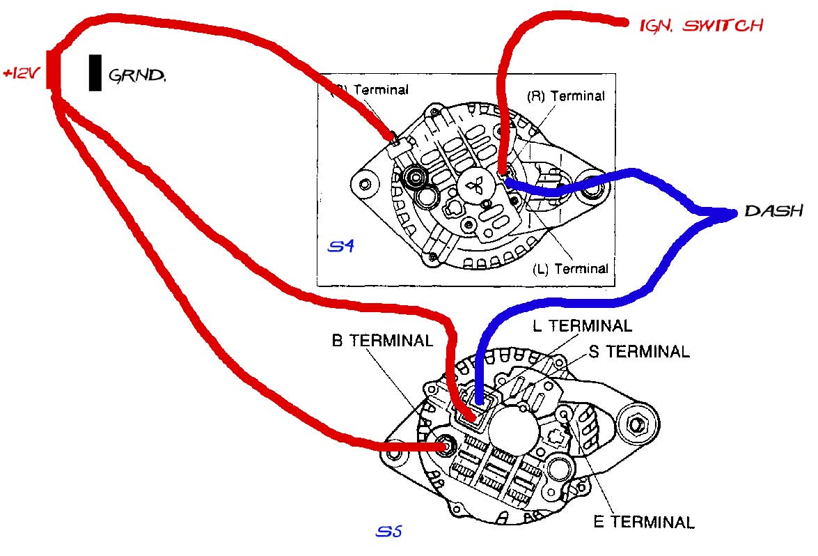
Car alternator wiring diagram. It requires advanced knowledge to fix an alternator with this diagram. It reveals the elements of the circuit as simplified forms and the power and also signal connections in between the tools. If you car has one. If you are able to look at a manufacturers diagram of the alternators connectors the wire that slides over pin 1 of the alternator leads to the positive connection on the vehicles battery and senses voltage. The other terminal is the exciter. The alternator charge wire routes direct to the battery and not through any switch connection the alternator will not operate correctly if not connected direct to battery or directly through the ammeter.
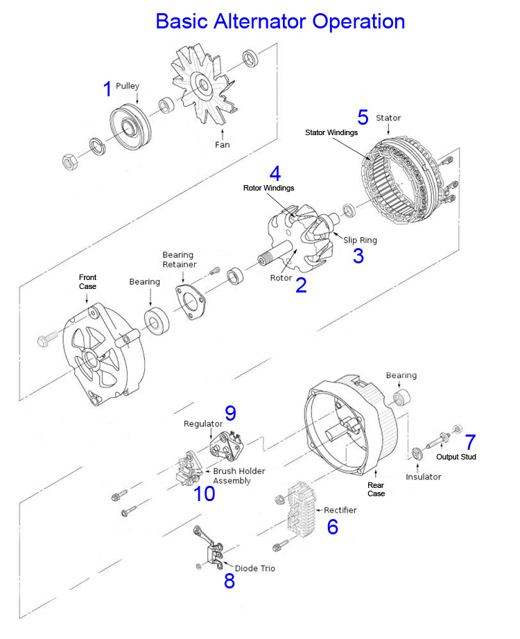
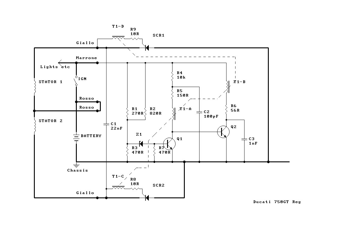
This rotor spins past wire coils causing a magnetic field. This wire will be either brown or brown with a colored stripe in a triumph. The stator contains the three phase armature winding and the rotor contains field winding. Autorestomod manic mechanic gasoline media 35312 views. All internally regulated alternators have the same basic electrical connections. As you see there are the three phase alternator is used in the car.
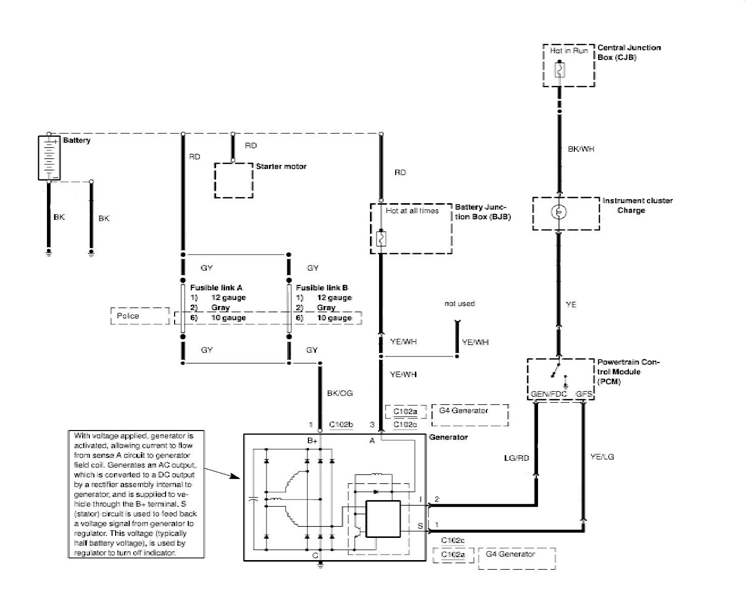
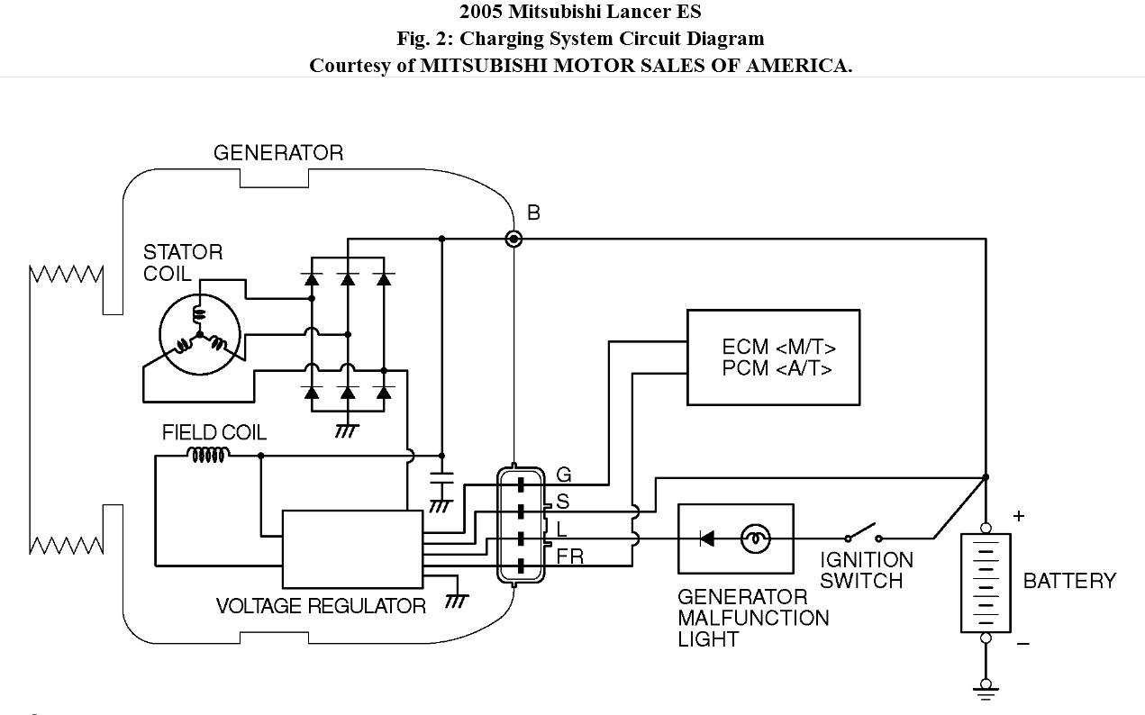
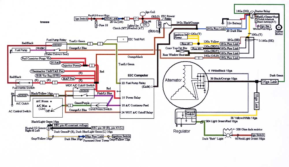
How alternator works diy voltage regulator. Among all the ford alternator wiring diagrams above this is the most complicated one. Figure 1 below is a block diagram or a functional diagram of an alternator and its connections to the remainder of the automobile electrical system. Collection of denso alternator wiring schematic. By comparing the descriptions below it will be easy to change the instructions to suit the alternator you have chosen. A wiring diagram is a simplified traditional pictorial depiction of an electrical circuit.
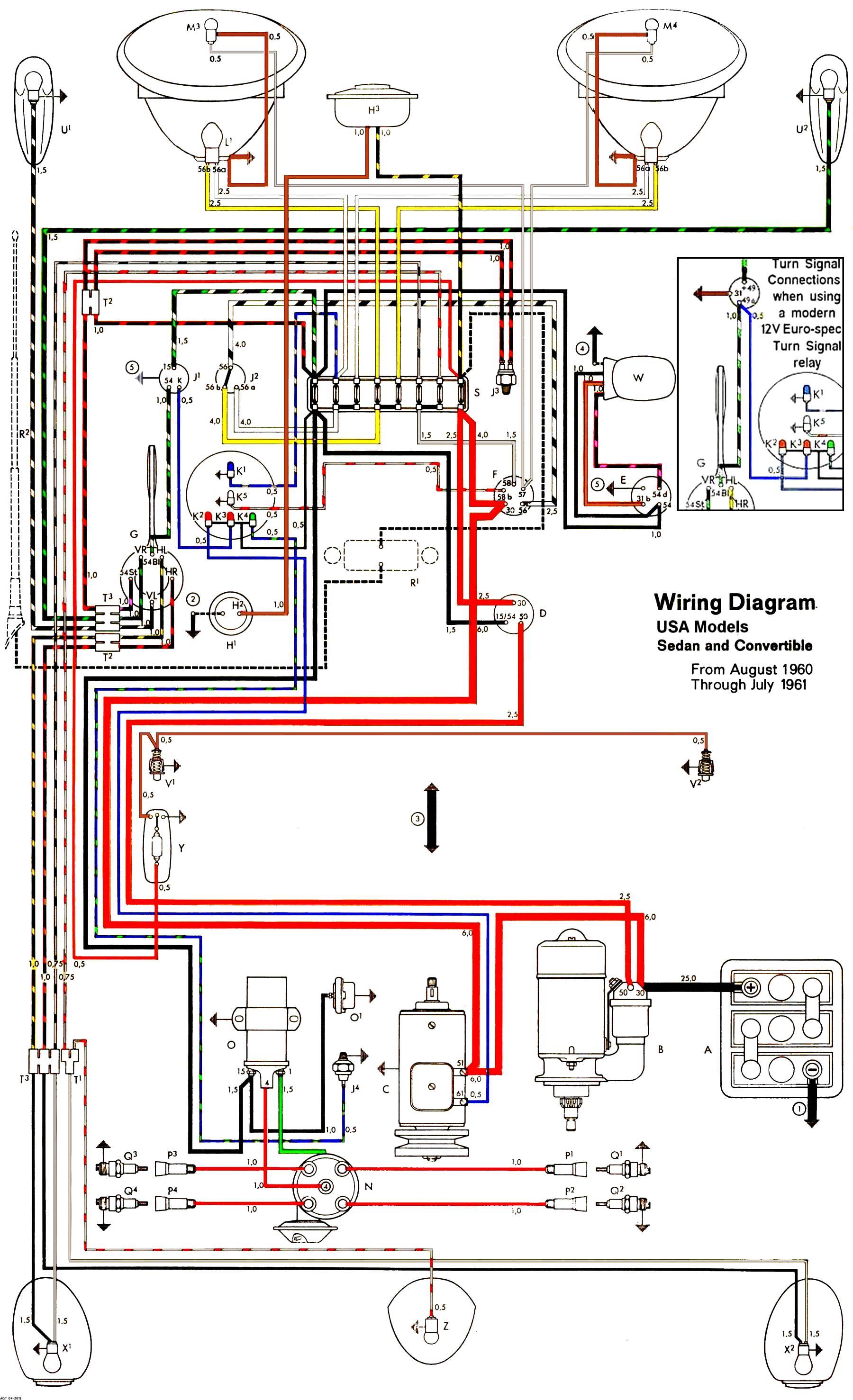
Free ford wiring diagrams difference between automatic and manual cars. It consists of ignition switch fuse panel engine compartment relay box instrument cluster and many more. The three phase alternator has two parts stator and rotor. The wiring that comes with our kits should be used as it is sized to handle the amperage. Trailer wiring diagram electrical circuit diagram trailer coupler 4x4 electrical projects electric cars wire vehicle repair car repair wiring a 3 wire alternator with an idiot light great lakes 4x4. This connector is manufactured so it may be inserted into the connector socket on the alternator one way only.
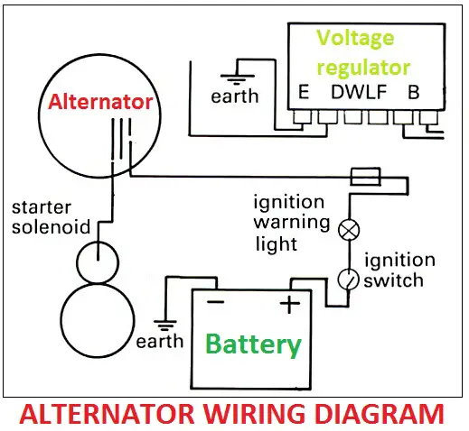
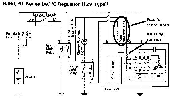
Here the basic internal circuit diagram of the car alternator and the wiring diagram of the alternator with battery is given below.
Gallery of Car Alternator Wiring Diagram