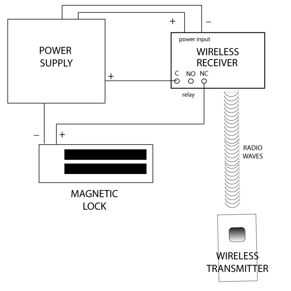
It shows the components of the circuit as simplified shapes and also the power as well as signal connections in between the gadgets. All rci electromagnetic locks must be powered with filtered and regulated dc power supplies such as the rci 10 series ul listed.

Solve The Problem Sticky Maglock
Electromagnetic door lock wiring diagram. Wiring diagram electromagnetic door lock em lock push button power supply 12v carane ngonek kunci magnet. Seco larm electromagnetic lock table of contents. A door can be kept closed using the holding force of a low voltage magnet. Introduction installation features wiring diagram parts list maximum wiring distance specifications troubleshooting overview and installation applications warranty introduction. Ensure the electromagnetic lock is set for the correct voltage. The e 941sa series of electromagnetic locks is the ideal way to secure a door against unauthorized entry.
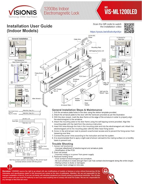
A p q b dc power supply no c magnet b pc board on 8011 002 q c no magnet a pc board on 8011 002 p nc. If low determine if the correct wire gauge is being used to prevent excessive voltage drop. It will give you a general idea of how the wiring should be completed while leaving out details such as mounting the components to a door or wall. 2 lock mounting anti tamper screw wiring cavity screw captive mounting bolts fig. Collection of magnetic door lock wiring diagram. There are two types of diagrams.
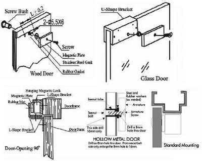
This guide will take you through the basics of connecting the components together. 3 anti tamper screw under wiring cavity note. The lock is usually mounted on the header above the door and the armature is usually mounted on the door see drawing below. 83718372 electromagnetic lock installation instructions continued 3 fig. Magnetic lock systems are fairly simple to set up. Magnetic lock setup guide introduction.
Assa abloys line of electro magnets is suited for high traffic applications as well as for easy installation on glass doors. Electromagnetic locks or fail safe strikes the strike is polarity insensitive 9 nc wiring instructions wiring for a man trap interlocking system. Electromagnetic locks are widely used in commercial and industrial applications. Even though most electromagnetic locking systems will include other components in the system the power supply is the one absolutely necessary component for any electromagnetic lock installation step 1 in design and approval is the wiring diagram. Remove any diode installed across the magnet for spike suppression. A wiring diagram is a streamlined conventional pictorial depiction of an electrical circuit.
Check for proper voltage at the electromagnetic locks input.
Gallery of Electromagnetic Door Lock Wiring Diagram