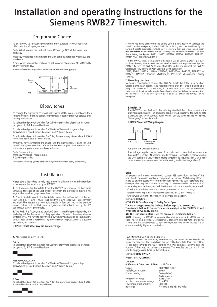
Rwb29 internal wiring diagram for more information see enclosed separate wiring and interchange sheet note. All external wiring must comply with current iee regulations.
C H Timer Wiring Help Please Diynot Forums
Siemens rwb27 wiring diagram. The rwb27 is supplied with the industry standard backplate to which the system must be wired. Wiring diagrams size 1 4. 3333 old milton parkway alpharetta ga 30005 siemens nema control 87 cut sheet1. Summary of contents for siemens rwb27 timeswitch page 1 note. Rwb27 internal wiring diagram for 240v link between l and 2 the voltage applied to terminal 2 is switched to terminal 4 when the timeswitch is in the on position and to terminal 3 when the timeswitch is in the off position. Low voltage switchgear and other power distribution equipment.
Rwb27 internal wiring diagram if 240v direct mains switching is required link l to 2. Use the tool below to quickly find and download one line diagrams. Wiring diagrams for typical tiastar units tool. Page 3 5 siemens industry inc. Siemens motor control center wiring diagrams are at your fingertips within seconds. If using the rwb27 to operate the pilot wire of a siemens electric bottom rear of the unit see fig.
1 into the relevant position for the style of panel heater link terminal l to terminal 2 and connect pilot wire to terminal operation you require. If 240v direct mains switching is required link l to 2. The backplate can be fitted directly to the wall or onto a conduit box. Only conduit boxes which comply with bs1363 or bs4662 single gang should be used. Wiring of this unit should be carried out by a competent electrician. Whilst every effort is made to ensure accuracy of the instructions given you will appreciate that.
Gallery of Siemens Rwb27 Wiring Diagram