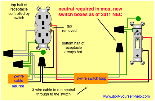
This diagram illustrates wiring for one switch to control 2 or more lights. The process is illustrated in sections or subsystems of the process called loops.
Why Do Industrial Sensors Measure In 4 20ma To Programmable
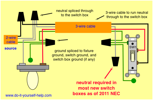
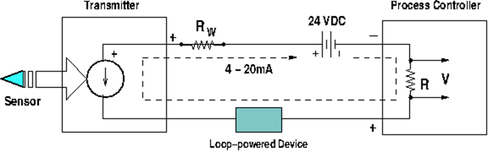
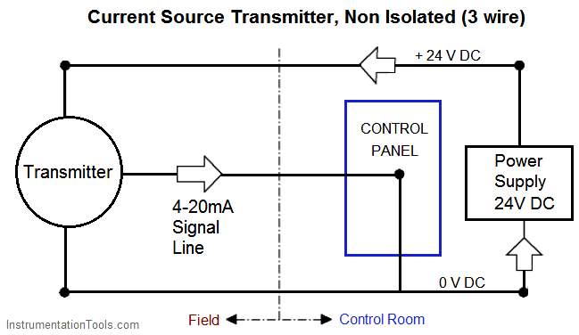
Loop wiring diagram examples. This is a typical wiring diagram of a loop powered signal isolator get energy from the input and 4 wire transmitter detailed parameters of loop powered signal isolator ato s sinir 502e are in the product page. It shows three cables. Although wiring data can be imported the intricate nature of instrumentation usually prevents a fully automated approach and so wiring is still performed manually to make sure it matches the intended design. Loop wiring diagram examples. Wiring diagram of loop powered isolator with external powered 4 wire transmitter. If it goes to the bulbholder this is called loop in wiring and the ceiling rose a junction box with a downward facing cable outlet then uses four sets of connections instead of 3 the extra one being a switched live.
The hot and neutral terminals on each fixture are spliced with a pigtail to the circuit wires which then continue on to the next light. A loop diagram will. Pids and loop diagrams pids and loop diagrams are construction and documentation drawings that depict the flow of the process and illustrate the instrumentation control and measurement interactions wiring and connections to the process. You can discover increasingly more experience as well as knowledge how the life is undergone. A switch loop single pole switches light dimmer and a few choices for wiring a outlet switch combo device. The loop wiring diagram examples content and also style of this circuitry representation truly will touch your heart.
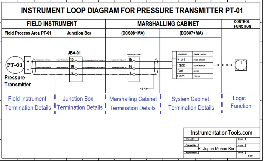
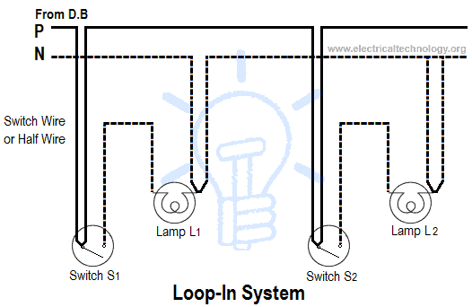
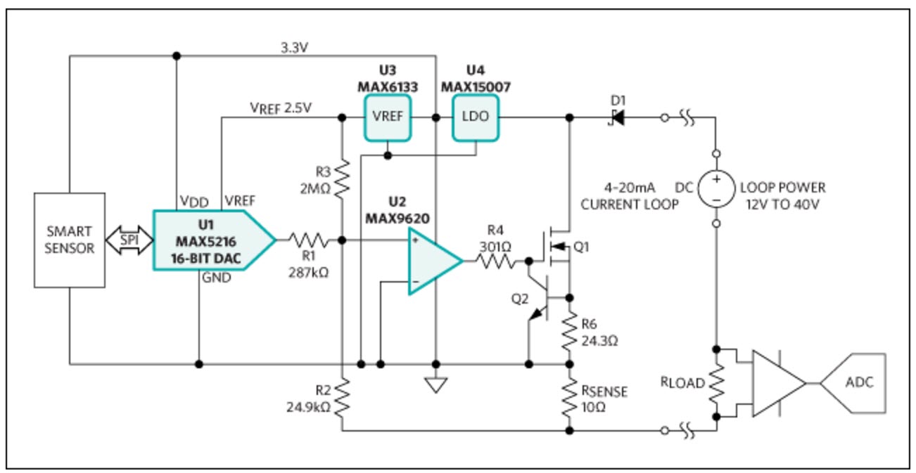
For example in our loop drawing below pdt pressure differential transmitter 42 has an input. We present loop wiring diagram examples here due to the fact that it will certainly be so very easy for you to access the net service. One cable lne either from the mains board or the last ceiling rose one cable lne out to the next ceiling rose and one cable lsl e that goes to the wall or pull switch within that room. Every instrument in a loop drawing has an input calibration and an output calibration specified for the instrument. 1a this is the most common loop in wiring arrangement you are likely to see. The power feed cable may go to either the switch or the bulbholder.
This page contains wiring diagrams for household light switches and includes. Instrument loop diagram that information is spread among many other documents and is not readily available. Loop drawing and wiring diagram conversion involves a semi automatic process. Also included are wiring arrangements for multiple light fixtures controlled by one switch two switches on one box and a split receptacle controlled by two. Cable numbers wire colours junction block numbers panel identification and grounding points are all shown in loop diagrams.
Gallery of Loop Wiring Diagram Examples