It500 user reference manual. Download salus controls manuals for all our thermostats programmers underfloor heating controls and smart home system.

Nl 7021 Cylinder Stat Wiring Download Diagram
Salus wiring diagram. Features three port option in 22mm and 28mm sizes removable actuator assembly manual lever and position indicator spring return industry standard wiring 4 sbmv32 instruction manual salus sbmv32 3 port 22mm manual green 005layout 1 06112013 12. 5push on the wires in the wall. 2mark the holes position for the wall box. Rt100 instruction manual 5 salus rt100 manual 00189 171110 1934. Carefully position any wiring back into the electrical box and secure the it500rx receiver using the existing screws. Page 7 salus ert20rf ver009qxd89 11032014 1117 strona 7 receiver wiring terminals terminal identifier description normally open no linked live feed 230v ac heating applications only live feed 230v ac neutral typical wiring installations avolt free installation notes.
Page 11 see the wiring diagram later on in this section. Salus controls is a member of the computime group ltd hong kong widely regarded for its electronic control technologies research design capabilities and manufacturing services. Mounting thereceiver onto optionalwall box. Reserve the right to always isolate the ac mains supply before change specification design and materials of installing this unit. 1remove the front cover of the receiver. Maintaining a policy of continual product development salus controls plc.
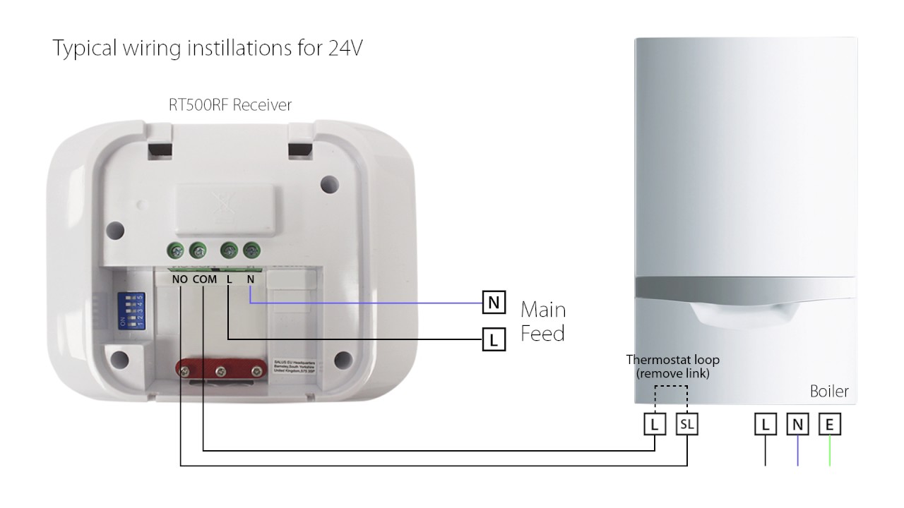
запчасти для газовых котлов и колонок в kotelkrua 189202 views. 7replace the front cover and installation is completed. терморегулятор salus 091 инструкция. Switchesjumpers wiring diagram prior to installing please read the wiring the receiver for the rt500rf installation guide for 230v. Salus controls offers both types of valve in a range of standard port sizes. Once the wiring has been completed position the it500rx receiver over the electrical box fixing holes.
View and download salus ct100 instruction manual online. Receiver unit should have a permanent 230v ac main supply. It occupies a unique niche in appliance heating air conditioning smart energy and building automation sectors serving customers in commercial industrial and. After passing the wiring through the cable entry point the rt100 can be secured into position by the use of two screws. 4connect the wires see wiring diagram. The terminals in the rt100 will accept conductor sizes between 05 mm2 15 mm2 and the cable ends should be stripped of no more than 8mm of insulation.
Ct100 thermostat pdf manual download. Securely fasten the receiver to the wall with the two screws. Find spec sheets for our products and quick guides on installation and how to use them.
Gallery of Salus Wiring Diagram