Remote sense wiring diagrams 35 602 figure 3. Fenwal ignition module part 35 605201 005.
120294 Manualzz
Fenwal ignition module wiring diagram. Remote flame sense cable must meet a voltage rating of 250v. Fenwal ignition module part 35 515505 117 obsolete no longer available 29400 21013. Local sense figure 2. Pn 06 237157 001 i june 2012 foreword this manual is intended to provide a general overview of the fenwal controls platform ignition module pim and its functions within a hydronic heating system when paired with a. Wiring the 35003 39 dc only control unit 22 d. Wiring errors can.
Wiring diagrams figure 1. Remote sense high voltage and remote sense cable requirements the hv ignition cable must meet a voltage rating of 25 kv and an insulation rating of 200 c. Wiring diagrams 35 61 figure 1. Sensor and ignition module must share a common ground with the burner. Design recommendations for use of fenwal cfd systems 1 8 2. 35 6086 56 pin caution label all wires prior to disconnection when ser vicing or replacing controls.
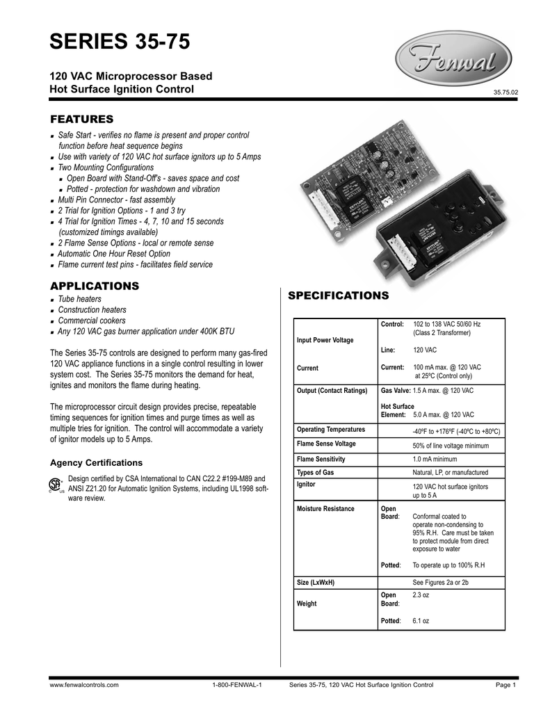
Any other wiring diagram you may have as colors on new wiring harnesses may not be in agreement with older wiring diagrams or harnesses. Mounting the control unit 20 b. Smaller footprint wiring diagram high voltage and remote sense cable requirements the hv ignition cable must meet a voltage rating of 25 kv and an insulation rating of 200 c. Wiring the 35003 38 acdc control unit 21 c. Handling and installing the sensing elements 23. A proven performer around the globe the 35 60 series has csa and ce approvals and uses 24vac 5060 hz inputs.
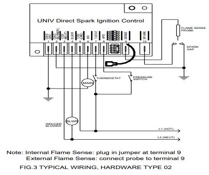
Choose from a wide range of voltages platforms and agency approvals for your application requirements. The ignition module controls the ignition coil or the firing time of that coil to ensure the ongoing efficiency of any heating product. This kit contains parts for replacing the fenwal ignition control on models btp 540a or btp 700a series 960 and earlier 962 series and 964 series. Consult factory for. Wiring diagrams 35 605 figure 1. Wiring diagram when connecting the 35 70 to other components in the system.
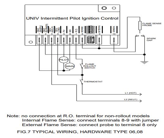
High voltage spark cables and control wiring harnesses are detailed on pages 5 and 6. Installation procedures for fenwal cfd system 20 a. The fenwal controls 35 60 series control gives you flexibility with multiple ignition types including direct spark ignition dsi intermittent pilot ip and dsi with inducer blower. Recommend length of 3ft 9m or less. Local sense figure 2. Recommend length of 3ft 9m or less.
Consult factory for longer lengths. The fenwal 35 608 series direct spark control 35 608 is a. Add to cart. Symptom control will not start up gas valve on and no spark through tfi spark on and gas valve off flame during trial for ignition but no flame sense after trial for ignition input power.
Gallery of Fenwal Ignition Module Wiring Diagram