View and download honeywell rm7895 series wiring diagrams online. Rm7895a1014 pdf manual download.

Honeywell Termostat Valve Honeywell
Rm7895a1014 wiring diagram. Keyboard display module 22 awg two wire twisted pair with ground or five wire. Recommended wire sizes and part numbers. Honeywell rm7895 microprocessor based integrated burner control provides on off primary control function and programmable pre ignition purge timing for automatically fired gas oil and combination fuel single burner applications. A the rm7890 and rm7895 must have an earth ground providing a connection between the wiring subbase and the control panel or equipment. Installation materials wiring conversion diagrams for rm7895 7800 series english product data and specifications product data for ec7895 rm7895 7800 series relay module english product data and specifications product data for rm7890 rm7895 100 vac 7800 series relay modules english. If you dont see the manual you need contact our customer service department.
The earth ground wire must be capable of conducting the current to blow a 15a fast blow type sc fuse. Rm7895abcd and rm7896abcd relay modules 3 66 2026 3 a the relay module must have an earth ground providing a connection between the subbase and the control panel or the equipment. On this page you will find downloadable pdf product manuals that have comprehensive instructions and guidance on installation and setup mounting calibration wiring instructions connections programming and repairs. 5 20 l1 hot 6. Rm7895 series computer hardware pdf manual download. Belden 8723 shielded cable or.
Line voltage alarm burner motor blower limits air flow switch pre ignition interlock pre purge is dependent on which st7800 timer is installed. Application wire size recommended recommended part numbers line voltage terminals. Rm7895 100 vac 7800 series relay modules 3 66 119501 table 1. View and download honeywell rm7895a1014 installation instructions manual online. 14 16 or 18 awg copper conductor 600 volt insulation moisture resistant wire. A wiring diagram is a simplified traditional pictorial depiction of an electric circuit.
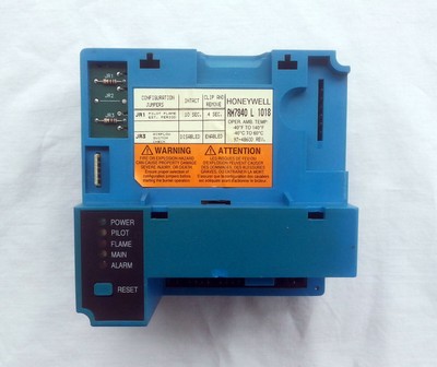
Rm7890 rm7895 terminal ratings. The earth ground wire must be capable of conducting th e current to blow the 20a fuse or breaker in event of an. See reverse side for rm7895a1014 wiring schematic 5 pre ignition interlock or jumper from terminal 5 5 5 provide line voltage input to terminal 19 for intermittent pilot operation. Rm7895a rm7895b rm7895c rm7895d. It shows the elements of the circuit as simplified forms as well as the power as well as signal connections between the tools. Collection of honeywell rm7840l1018 wiring diagram.
7800 series relay modules.
Gallery of Rm7895a1014 Wiring Diagram