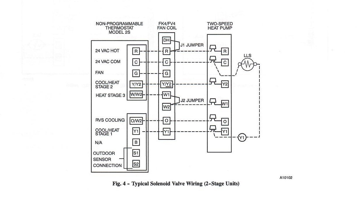
Wiring and fusing when used must comply with prevailing local and national wiring codes and ordinances. This illustrates which wires to connect for either 120 208 or 240 volt operation.
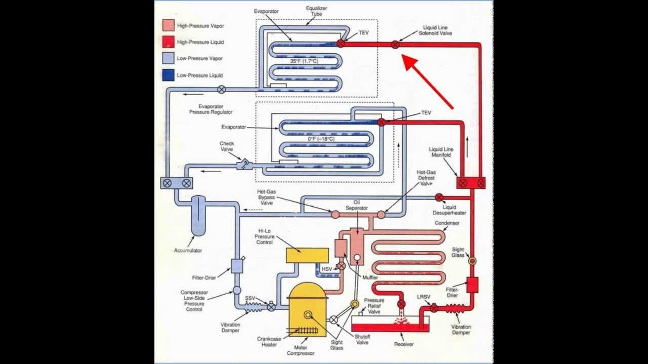
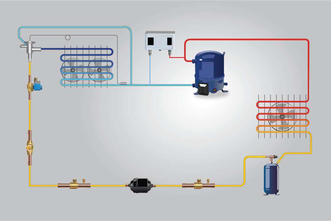
Rerfrigeration Pump Down
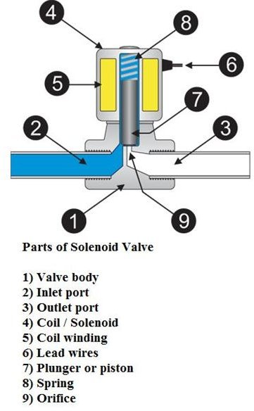
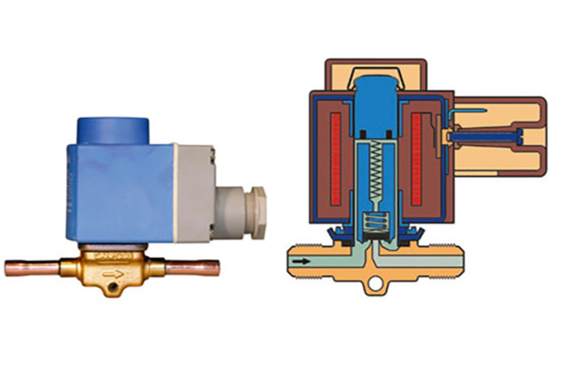
Liquid line solenoid valve wiring diagram. The application of a liquid line solenoid valve depends mainly on the method of wiring the valve with the compressor control circuit. 5 typical field wiring electronic arrangement thermostat liquid line solenoid valves and power notes. On multiple systems a solenoid valve may be used in each liquid line leading to the individual evaporators. Wiring and fusing when used must comply with prevailing local and national wiring codes and ordinances. A liquid line solenoid is just a valve that opens and closes it has a magnetic coil and depending on whether the valve is normally open or normally closed it opens or closes when the coil is energized. Solenoid valves with four wire dual voltage coils have a wiring diagram decal figure 3 on the coil housing or bracket.
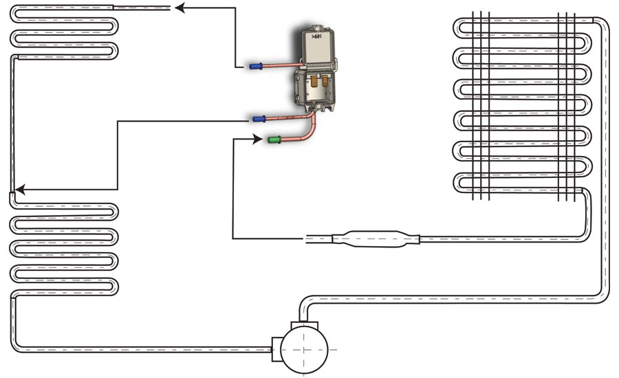
If you work on refrigeration or straight cool units up north you are likely very well acquainted with pump down solenoids. Solenoid valves me series bulletin 30 11 sd 15 3 way solenoid valves bulletin 30 21 sd 114. Asco valves have a solenoid mounted directly on the valve body. A solenoid valve is a combination of two basic functional units. This illustrates which wires to connect for either 120 208 or 240 volt operation. Later when the box thermostat calls for cooling it opens the liquid line solenoid valve allowing liquid to enter the metering device and into the low side.
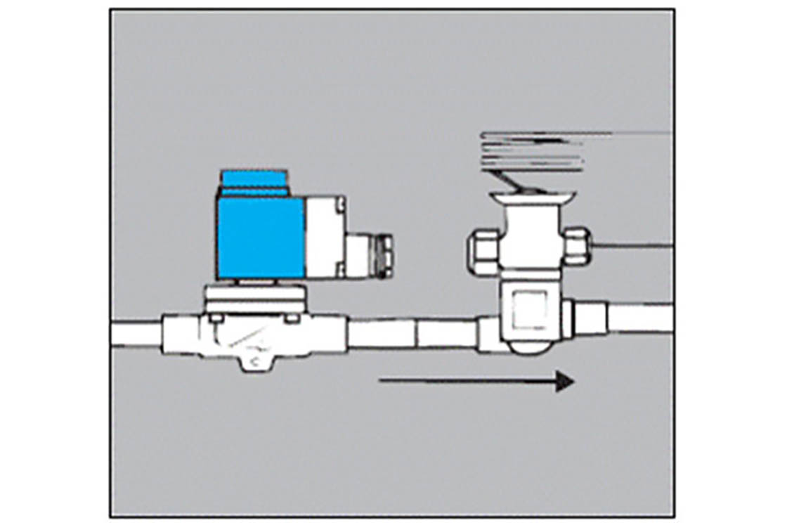
It also eliminates the possibility of refrigerant migrating to the compressor sump during the off cycle and washing out the oil at start up. This illustrates which wires to connect for either 120 208 or 240 volt operation. Solenoid valves with four wire dual voltage coils have a wiring diagram decal figure 3 on the coil housing or bracket. Factory wiring in accordance with the nec. The components of a pump down system are a lpc a t stat and a solenoid valve which is installed in the liquid line. This type of application is shown in fig.
Wiring and fusing when used must comply with prevailing local and national wiring codes and ordinances. The low side pressure increases until the low pressure control senses the cut in pressure 15 psig and then the compressor comes on. A solenoid electromagnet with its core a valve body containing one or more orifices flow through an orifice is shut off or allowed by the movement of the core when the solenoid is energized or de energized. It may be wired so the valve is energized only when the compressor is running. When installed in that location it is called llsv for liquid line solenoid valve. Solenoid valves with four wire dual voltage coils have a wiring diagram decal figure 3 on the coil housing or bracket.
Gallery of Liquid Line Solenoid Valve Wiring Diagram