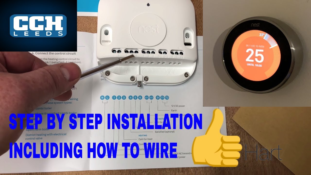
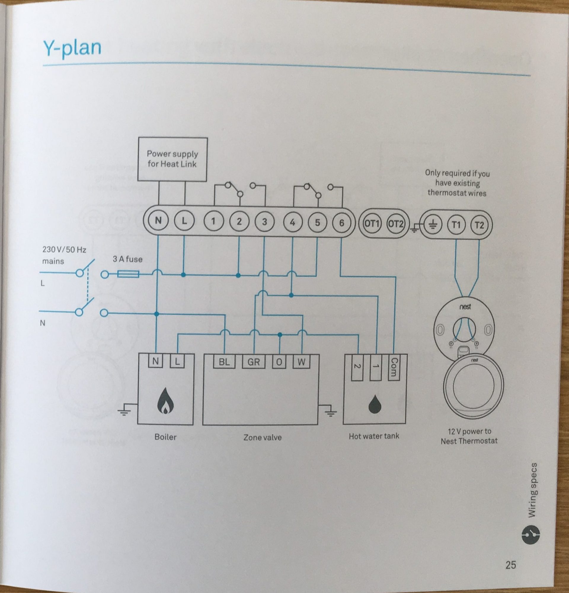
Spadgefox 24 dec 2016 in forum. Attached is the wiring diagram for the receiver.

1974 Spitfire Wiring Diagram Wiring Diagram
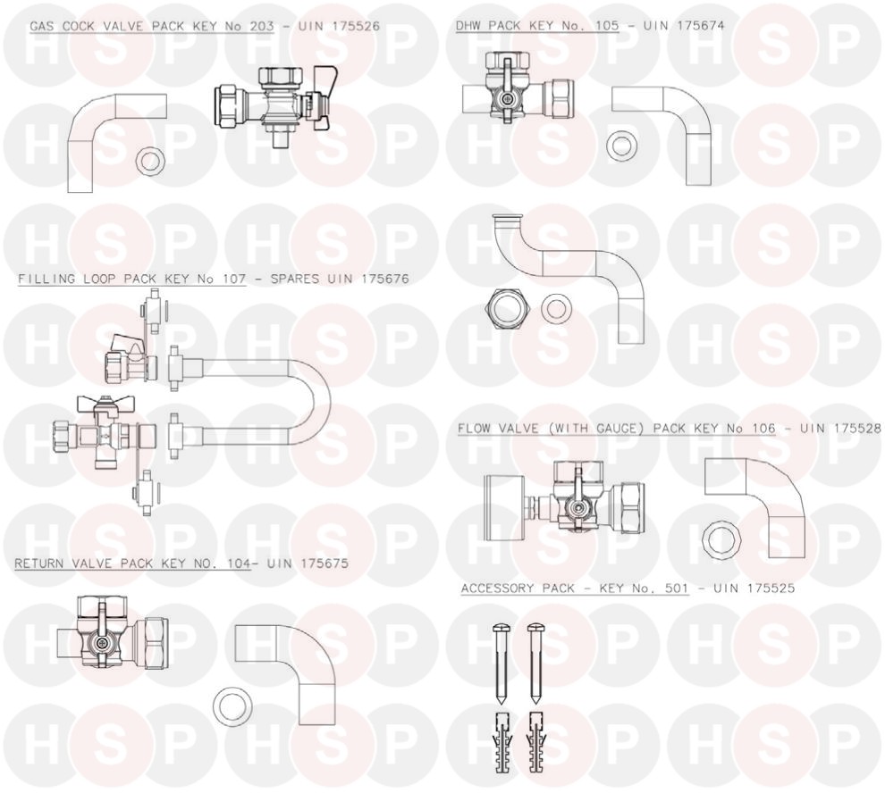
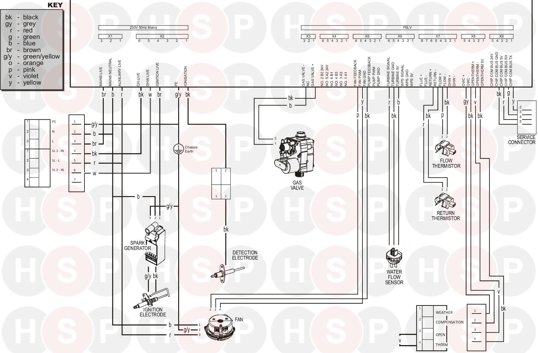
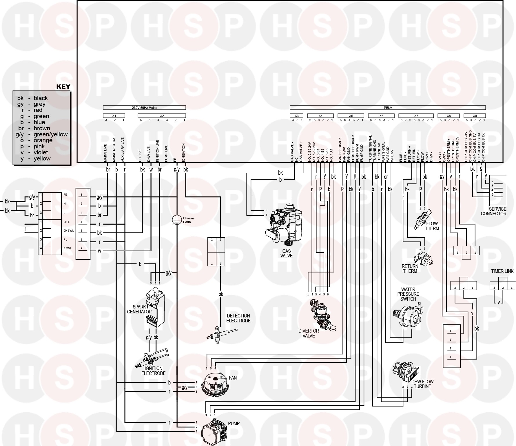
Ideal logic combi 30 wiring diagram. I have an ideal logic 30 combi boiler and had a honeywell r6660d receiver and simple wireless thermostat. Do not use reconditioned or copy parts that have not been clearly authorised by ideal. Bottom iet wiring and the regulations boiler. Ideal logic combi 30 pdf user manuals. View online or download ideal logic combi 30 user manual. Boiler diagrams spare parts and user manuals for ideal logic combi 24 boiler exploded view 24 hour delivery on genuine manufacturer boiler spares 30 day money back guarantee.
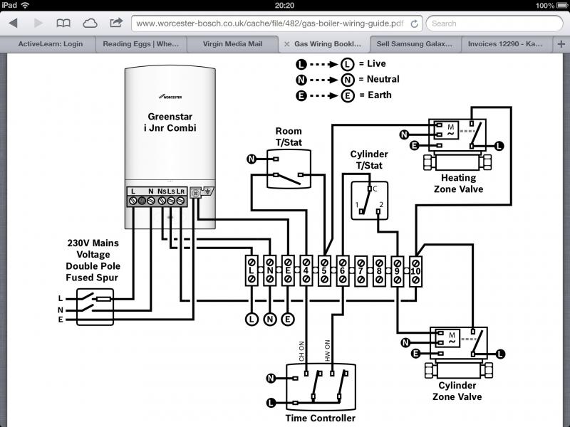
Boiler diagrams spare parts and user manuals for ideal logic combi 30 wiring diagram 24 hour delivery on genuine manufacturer boiler spares 30 day money back guarantee. Based on the diagram below from the logic 30 boiler manual. Ideal logic combi esp1 24 30 35. Logic combi 24 boiler pdf manual download. Hive with logic combi 30 wiring problems. Just google s plan or whichever wiring diagram and click on images.
Jgeorge 4 jan 2020 in forum. 2 ideal logic combi users minimum clearances clearances of 165mm 6 12 above 100mm 4 below 25mm 18 at the sides and 450mm 17 34 at the front of the boiler casing must be allowed for servicing. And the hive single channel receiver needs 6 e n l 1 2 3. Boilers central heating boilers new boilers ideal boilers. This must be obtained with an easily removable panel to. Bottom clearance bottom clearance after installation can be reduced to 5mm.
Logic combi 35 logic combi 30. Plumbing and central heating. Logic combi c 24 30 35 when replacing any part on this appliance use only spare parts that you can be assured conform to the safety and performance specification that we require. Plumbing and central. Hive to ideal logic combi c30. As you can see it only has 5 wires earth live neutral t1 t2.
View and download ideal logic combi 24 installation and servicing online.
Gallery of Ideal Logic Combi 30 Wiring Diagram