Current australian colour code single phase. This video is a step by step tutorial on how to wire the pir motion sensor.

Toyota Avalon Camry Camry Solara 2001 06 Wiring Diagrams
Sensor light wiring diagram australia. Wiring diagram will come with a number of easy to follow wiring diagram directions. Each component should be placed and linked to other parts in specific manner. The list below outlines what the different colour codes mean for both single and multi phased. The sensors i used were made of plastic so did not require the ground wire to be connected. Pet motion detector wiring diagram 476 today wiring diagram motion sensor wiring diagram. If not the structure will not function as it ought to be.
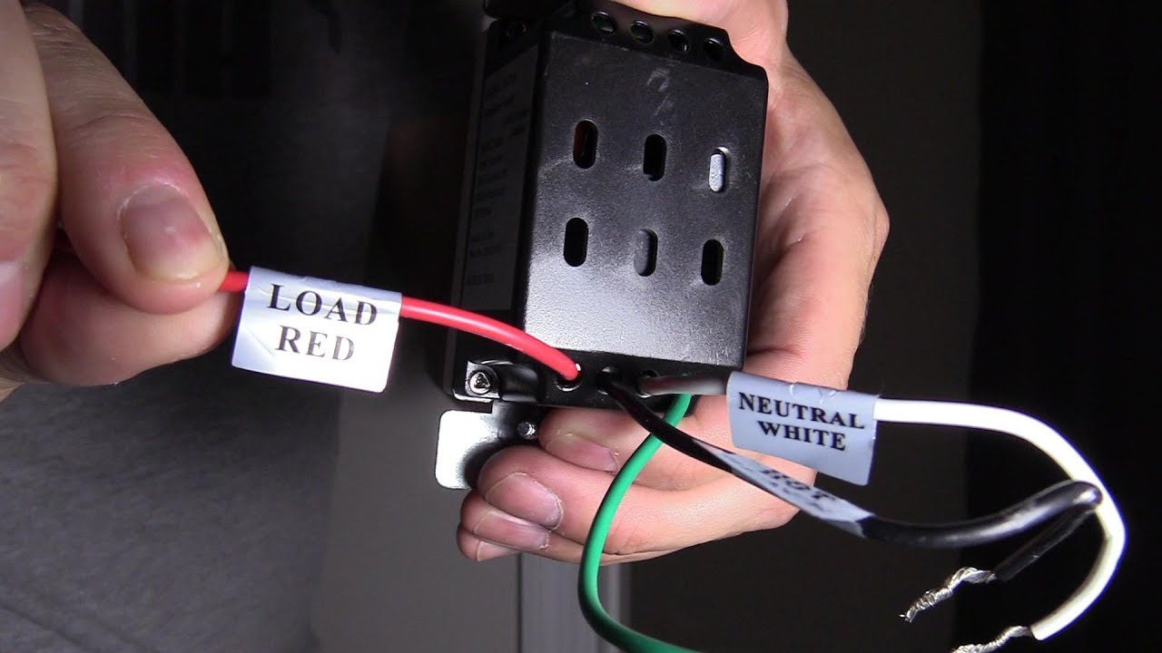
The ground wire is required if the light housing is of metal construction to ground the fitting if it did become live. Direct the sensor toward the desired area to be scanned. To achieve best results for outside use the arlec security sensor should be mounted on a wall or under eaves of a building generally used to control an existing light fitting. There are some limitations to this system. It reveals the elements of the circuit as streamlined shapes and also the power and also signal connections between the tools. Just screw the receiver into a light socket and mount the sensor anywhere you like.
Wireless motion sensor lights a wireless sensor works like the remote control for a garage door opener. In australia the wiring code colors should be red positive black negative greenyellow ground. Strip approximately 6 8mm insulation from the cables for insertion into the terminal block. Active brown neutral light blue earth greenyellow. Variety of motion sensor light wiring diagram. It sends a radio signal to a receiver that switches on a light.
Route cable from the lights and cable from the power source to the terminal block. It really is intended to assist all of the common user in developing a correct program. Light switch wiring diagram light switch wiring diagram 2 gang light switch wiring diagram 2 switches 1 light light switch wiring diagram 3 way light switch wiring diagram australia light switch wiring diagram l1 l2 light switch wiring diagram nz light switch wiring diagram pdf light switch wiring diagram red wire light switch. Ideally the security sensor should be mounted 24 metres 8ft above the area to be scanned refer fig1a. Phase 1 brown phase 2 black. No wiring is necessary to control existing lights.
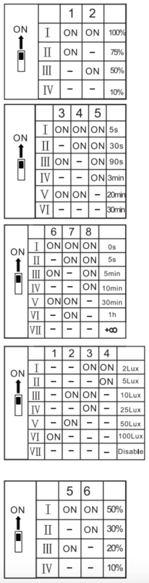
Correct wiring probably saves an expensive pir sensor from an irrecoverable malfunction and annulment of any warranty terms. Equipment wiring includes things such as wiring in power cords. Under eave if possible. Wiring diagram red brown blue l n l wiring to terminal block. Current australian colour code multiphase. Wiring a motion sensor light diagram motion sensor light wiring diagram australia wiring a motion sensor light diagram wiring a motion sensor light diagram uk every electrical arrangement is composed of various diverse pieces.
A wiring diagram is a simplified conventional pictorial depiction of an electrical circuit. These instructions will likely be easy to understand and use.
Gallery of Sensor Light Wiring Diagram Australia