The plinth was a mess and pully had dents in it. The atlas turntable and track polarity.

Marantz Tt 8001 Turntable Record Player On Demand Pdf Download Japanese
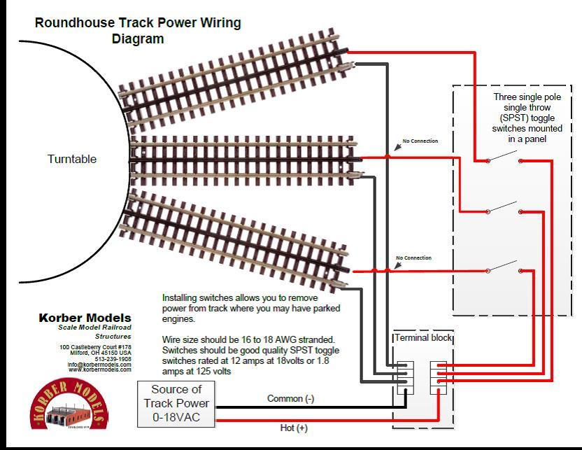
Turntable wiring diagram. You must fix the position of your service tracks before you program the positions. July 7th we are 100 open. B1 and b2 connect to rail power supply. How do you wire a turntable headshell. Replace faulty turntable headshells and wiring to ensure clear crisp sound from your vinyl records. The official online store for the atlas model railroad company inc.
The wiring from the tone arm had been torn from the terminal connector under the base. I got my turntable today and started to look at it. Shop audiophile dual garrard pioneer sony more. Audio technica cartridge wiring follows standard four pin sme type headshell wiring convention. In this example i am using the numark hs 1 headshell with the altai hl hm160 cartridge to show it is wired. This particular headshell is a standard sme type with a h 4 bayonet mount.
Audio technica cartridge wiring follows standard four pin sme type headshell wiring convention. Install the safety guard before installing the leads and always follow best practices stated in the manufacturer documentation. Heres a diagram of the wiring. This cartridge also known as groovetool uses the widely accepted pinout standard. The early mrm acdc decks bottom diagram with a bicolour led at the front had a transistor and resistor soldered to it but i dont remember the values nor how it was configured and supplied with power. To match radial tracks you can reverse polarity by interchanging the b1 and b2.
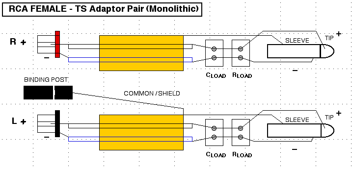
With many turntables some of these adjustments may not be necessary or possible the next step is to fit the four coloured wires to the pins on the cartridge as shown. Turntable headshell wiring diagram. Install the safety guard before installing the leads and always. Manufacturer and seller of model trains and track in n ho o and z scales. Flip up the turntable and wire the rca jacks. When wiring an atlas turntable for dc operation the tracks in the turntable area must be wired so the plus and minus the polarity of the rails on the turntable will match that of the tracks it is lined up with.
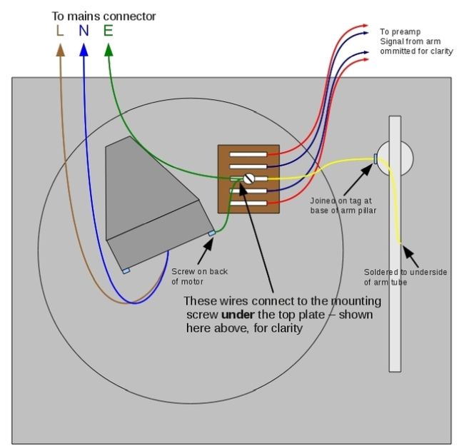
Wire the service tracks parts not included for power as desired. Turntable wiring diagram here is a scrappy sketch of the various wiring layouts in the source. Connection points are marked on the underside as follows. Otherwise there will be a short circuit when the locomotive attempts to move on or off the turntable. Now i have a few questions. Connection wiring diagram please note that your dcc turntable automatically reverses the track polarity in the no track area.
Now the real fun beginsthe infamous ar tone arm damping system.
Gallery of Turntable Wiring Diagram