Search through our list of wiring diagrams to find the right one for your job. A wiring diagram is a simple visual representation of the physical connections and physical layout of your electrical system or circuit.

400 Amp Pedestal Fulton County Remc
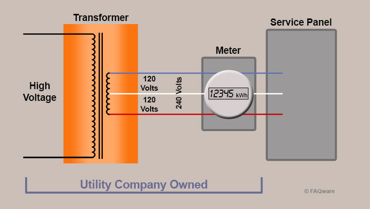
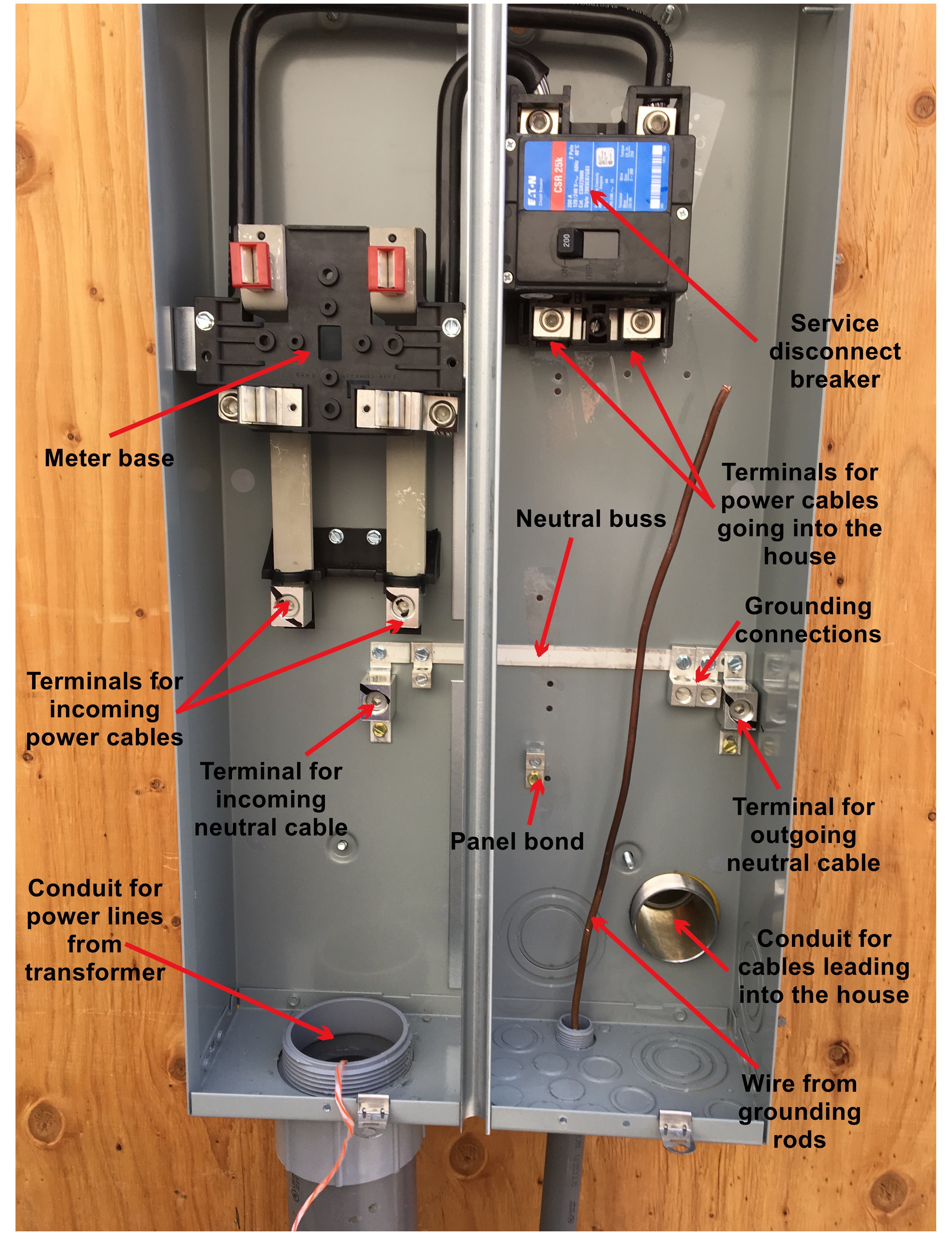
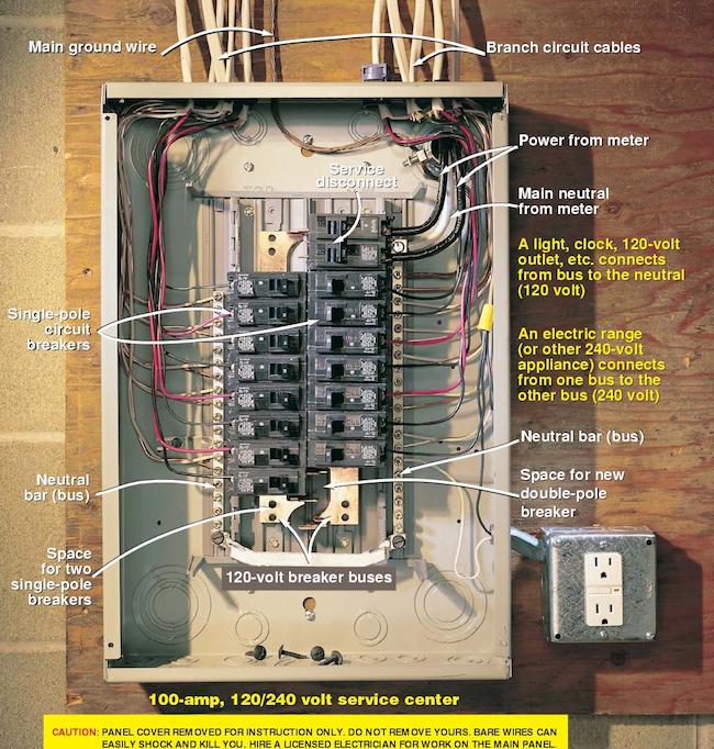
Meter panel wiring diagram. Due to the meters design it is not possible for the meter power source to share ground with the input. Electric meter box wiring diagram what is a wiring diagram. Order our 240 volt meter. Electric meter box wiring diagram. Click here to view and print the full size diagram. A wiring diagram is a simplified standard pictorial representation of an electrical circuit.
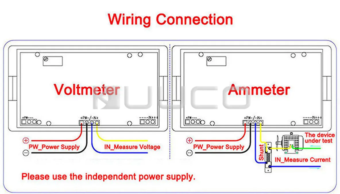
Single phase form 2s for 120v circuit. It shows what sort of electrical wires are interconnected which enable it to also show where fixtures and components may be coupled to the system. In this example the meter is wired to manufacturer specifications where a separate power source such as a completely separate battery is solely used to power the meter. Electric meter box wiring diagram architectural electrical wiring layouts reveal the approximate areas and also interconnections of receptacles lighting as well as permanent electrical solutions in a structure. It reveals the parts of the circuit as streamlined forms and also the power and signal connections between the tools. As with the line connection the load connection has the two hot feeds as well as a center neutral connection.
This is the portion of the meter that feeds the main service panel or the electrical disconnect. There is also a 6 gauge ground wire that links the neutralground connection on the meter to the grounding rod. Variety of electric meter box wiring diagram. This diagram shows how to wire it for 120v. Form 2s need a meter for a 120 volt circuit. Single phase form 2s for 240v circuit.
Gallery of Meter Panel Wiring Diagram