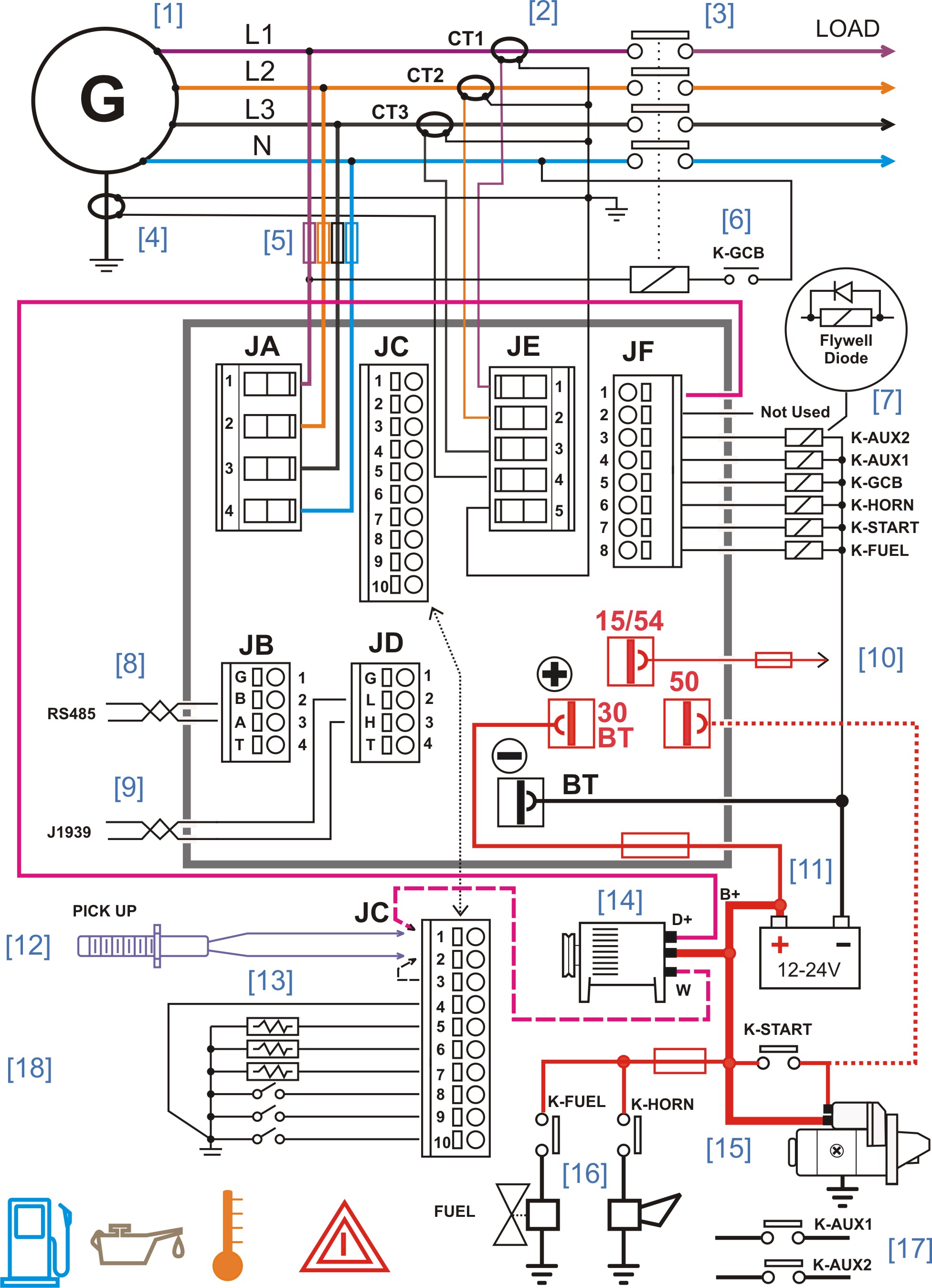
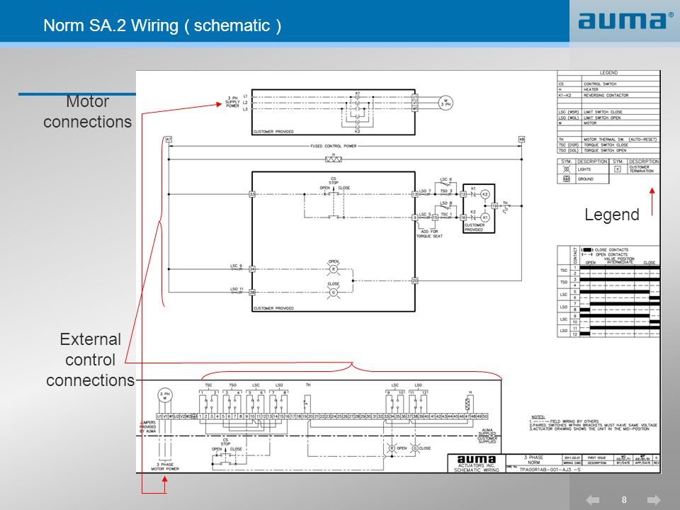
Wiring diagram for standard version multi turn actuator closes valve clockwise. Wiring diagram nomenclature table.
Auma Fergo Armaturen Gmbh
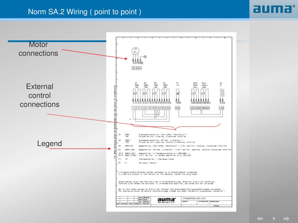
Auma wiring diagram. If the pop up blocker is turned on in your browser you are not able to view the wiring diagram. The wiring diagram service provides the wiring diagrams for our products according to. The wiring diagram shows the non rotating multi turn actuator in intermediate position. Electrical connection 15 81 connection with auma plug socket connector s sh se 17 9. Manual operation 19 10. The wiring diagram opens in a pop up window.
If the pop up blocker is turned on in your browser you are not able to view the. Transport storage and packaging 10 51 transport 10 52 storage 10 53 packaging 11 6. Column ordering code remarks 14. The wiring diagram opens in a pop up window. Wiring diagram number quotation number. Extract of wiring diagram code posi tion 1234567891011121314 position tpa0 0 r 1 a a 101 000 1 2 00 auma 3 ph ac motor 01 auma 1 ph ac motor for sa 2sq 2 16 1 ph ac motor for sg 1 3 r clockwise closing l counterclockwise closing 4 1 1 thermoswitch 140 c nc 2 1 kaltleiter 5 0 without torque switches mwg a 2 single switches standard b 2 tandem switches 6 0 without limit.
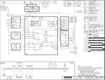
Mounting to valve gearbox 12 7. Column wiring diagram number explanations 2. Selected wiring diagrams under documents attention. Selected wiring diagrams under documents attention. Io interface 1 4 digital inputs close open stop emergency 6 digital outputs standard 2 4 digital inputs close open stop emergency 6 digital outputs. Mounting positions of the local controls 14 8.
Wiring diagram number quotation number. M motor 3 phase ac s 1 dsr torque switch closing clockwise s 2 doel torque switch opening counterclockwise s 3 wsr limit switch closing clockwise s 4 woel limit switch opening counterclockwise s 5 bl blinker transmitter f 1 th thermoswitch q 1 main switch s 8 push button stop s 9 push button close s 10 push button. Please enter the address of our website in the address of web site to allow box. Additional information to the wiring diagram legend 9 5.
Gallery of Auma Wiring Diagram