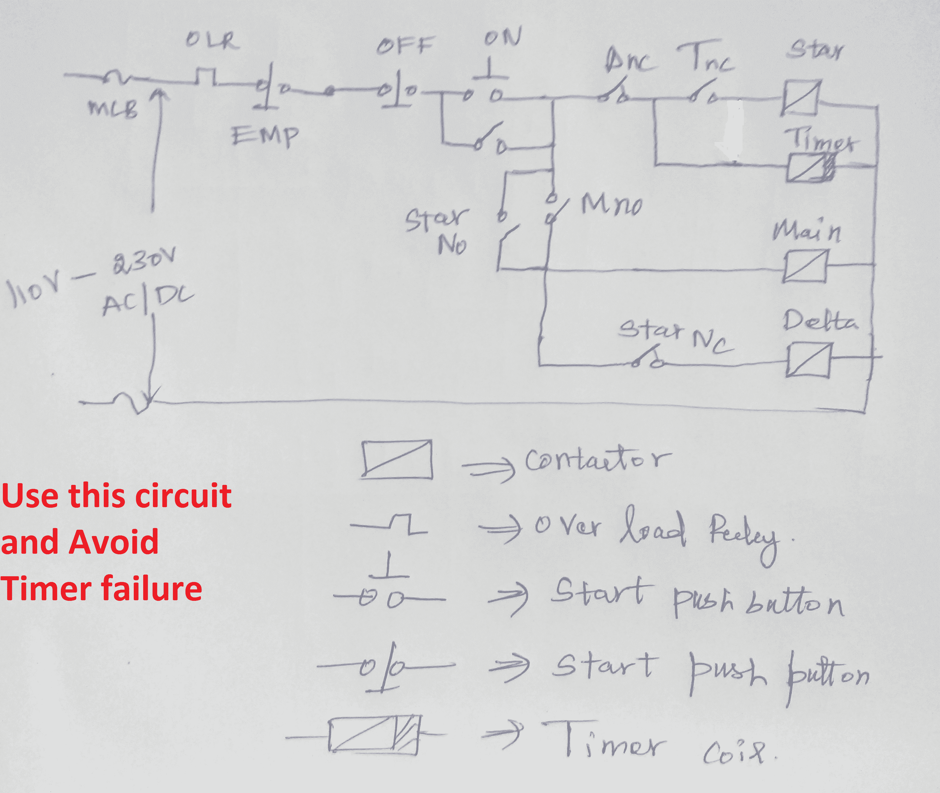
In the above star delta starter control circuit wiring diagram with timer and normally close push buttonnormally open push button switch. Direct on line dol wiring diagram for 3 phase with 110230vac control circuit elec eng world.

Star Delta Starters Explained The Engineering Mindset
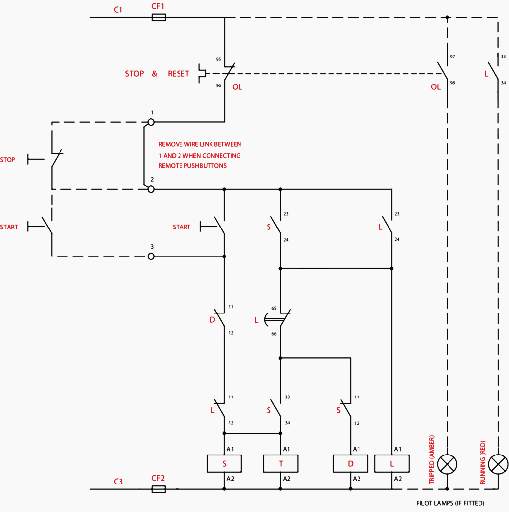
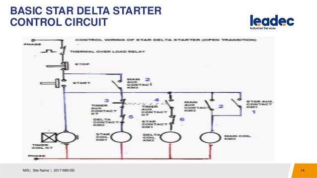
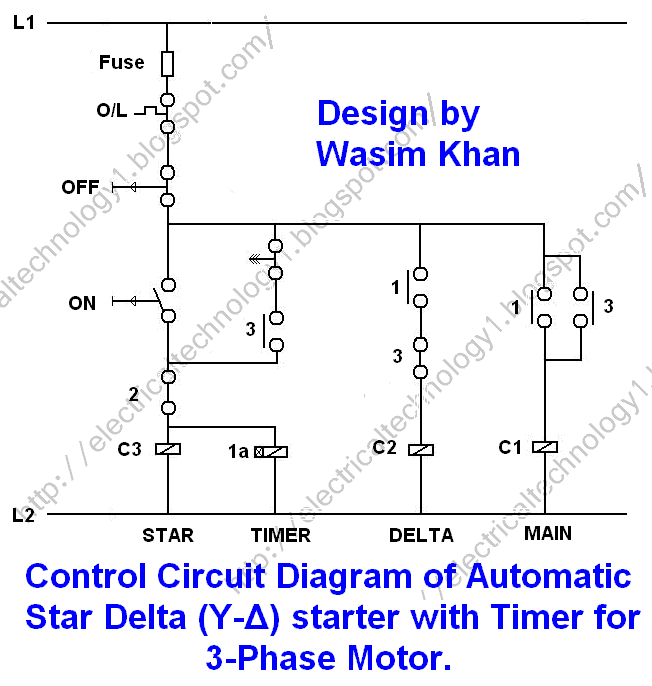
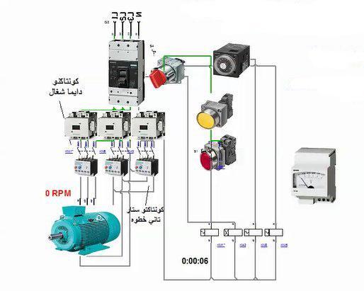
Star delta control wiring diagram. Star delta starters consist of a power circuit and control circuit. Control wiring of star delta starter with diagram wiring diagram is a simplified adequate pictorial representation of an electrical circuit. A 8 pin timer are used. Power control wiring diagram of star delta starter. The on delay timer diagram is also shown in the diagram. The control circuit uses to control the starter circuit such as on off and tripping operations.
The on delay timer diagram is also shown in the diagram. In this tutorial we will show the star delta y δ 3 phase induction ac motor starting method by automatic star delta starter with timer with schematic power control and wiring diagram as well as how star delta starter works and their applications with advantages and disadvantages. The star delta wye delta starting method controls whether the lead connections from the motor are configured in a star or delta electrical connection. In control wiring diagram all magnetic contactors coils are rated 220 vac. Star delta starter control wiring. Next the circuit goes through the nc terminals of the thermal over load relay.
A 8 pin timer are used. R y b red yellow blue 3 phase linescb general circuit breakermain mai supplyy starδ deltac1 c2 c3 contatcors power diagramol over load relayno normally opennc normally closed k1 contactor contactor coil k1no contactor holding coil normally openk1 k2 k3 contators for control diagram. Electronic engineering electrical engineering ac wiring electrical circuit diagram electric circuit heavy and light electrical installation heartbroken quotes electronics projects. One is power circuit and another one is control circuit. In the above star delta starter control circuit wiring diagram with timer and normally close push buttonnormally open push button switch. The initial connection should be in the star pattern that results in a reduction of the line voltage by a factor of 13 577 to the motor and the current is reduced.
As you see in the above star delta starter diagram first an nc push button switch is connected to stop the operation. Star delta connection circuit diagram. It shows the components of the circuit as simplified shapes and the capability and signal connections amongst the devices. The power circuit uses to create contact between the motor and three phase power supply. Here you can see the control circuit diagram of automatic star delta starter. In control wiring diagram all magnetic contactors coils are rated 220 vac.
Gallery of Star Delta Control Wiring Diagram