Set manually 51 3 actuator controls ac 012acexc 012 profibus table of contents. Additional information to the wiring diagram legend 9 5.
20 Inspirational Auma Actuator Wiring Diagram
Auma actuator control wiring diagram. Selected wiring diagrams under documents attention. Transport storage and. The wiring diagram opens in a pop up window. The auma matic allows automated valves to be integrated into a wide variety of control systems. Combinations with spur gearboxes. Please enter the address of our website in the address of web site to allow box.
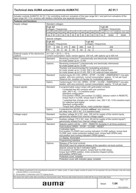
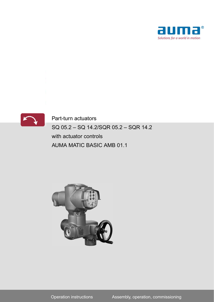
Operation instructions assembly operation commissioning for actuator. Technical data 6 4. Actuators of the sa type range for open close duty and positioning duty are rated for class a and b or types of duty s2 15 mina special version for longer running is available for the s2 30 min duty. If the pop up blocker is turned on in your browser you are not able to view the wiring diagram. Combinations with spur gearboxes. The modulating actuators of the sar range are rated for class c or types of duty s4 25 special versions for s4 50 and s5 25 are also available.
Actuators sa uw and sar uw. Auma riester gmbh co. Switch on or off 50 843. With actuator controls auma matic am 011 am 021 operation instructions table of contents page 1. Short description 5 3. Proposed wiring diagram for external sensors 3 wire technology 59.
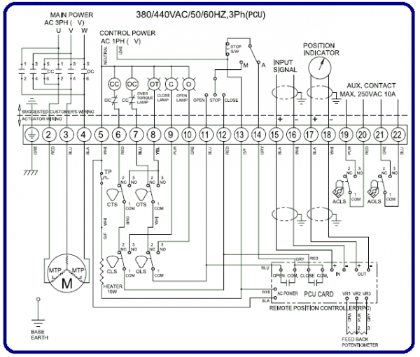
1 d 79379 muellheim. Auma actuator controls are exclusively designed for the operation of auma actuators. The auma matic integral motor controls offer modern and economical actuator control technology. Explosion proof variable speed actuators savex and sarvex. Wiring diagram number quotation number. Reversing starters control voltage power supply and pilot devices pushbuttons indicating lights and selector switch are standard components.
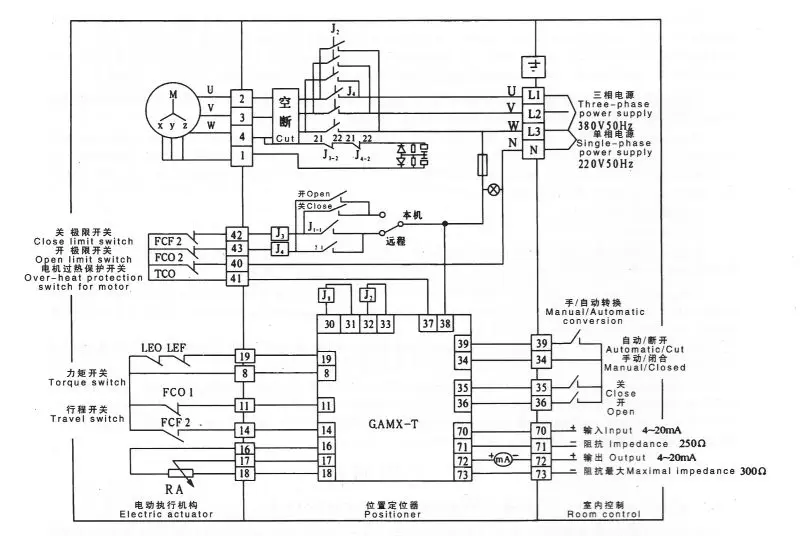
Table of contents page 1. Overrun inner dead band. Explosion proof variable speed actuators savex and sarvex. Control devices such as a plc or pc communicate via a fast serial connection with. M motor 3 phase ac s 1 dsr torque switch closing clockwise s 2 doel torque switch opening counterclockwise s 3 wsr limit switch closing clockwise s 4 woel limit switch opening counterclockwise s 5 bl blinker transmitter f 1 th thermoswitch q 1 main switch s 8 push button stop s 9 push button close s 10 push button open k 1 k 2 reversing contactors f 2 f 5 fuses h 1 indication light end. Safety instructions 4 11 range of application 4 12 electrical connection 4 13 maintenance 4 14 warnings and notes 4 2.
Proposed wiring diagram for external sensors 2 wire technology 58 82. Positioner operation mode remote setpoint 50 841. The wiring diagram shows the non rotating multi turn actuator in intermediate position. Actuators sa uw and sar uw. Two wire control 49 84.
Gallery of Auma Actuator Control Wiring Diagram