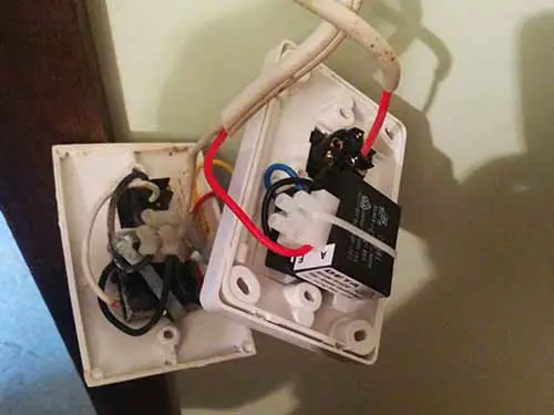
Page 4 optional relay overrides temp sensor and turns on fans when ac is turned on battery 86 30 87 85 86. The common on the second 3 way switch is connected to the hot wires on the fanlight.

Parking Ventilation Systems Air Trade Centre Hvac Cozumleri
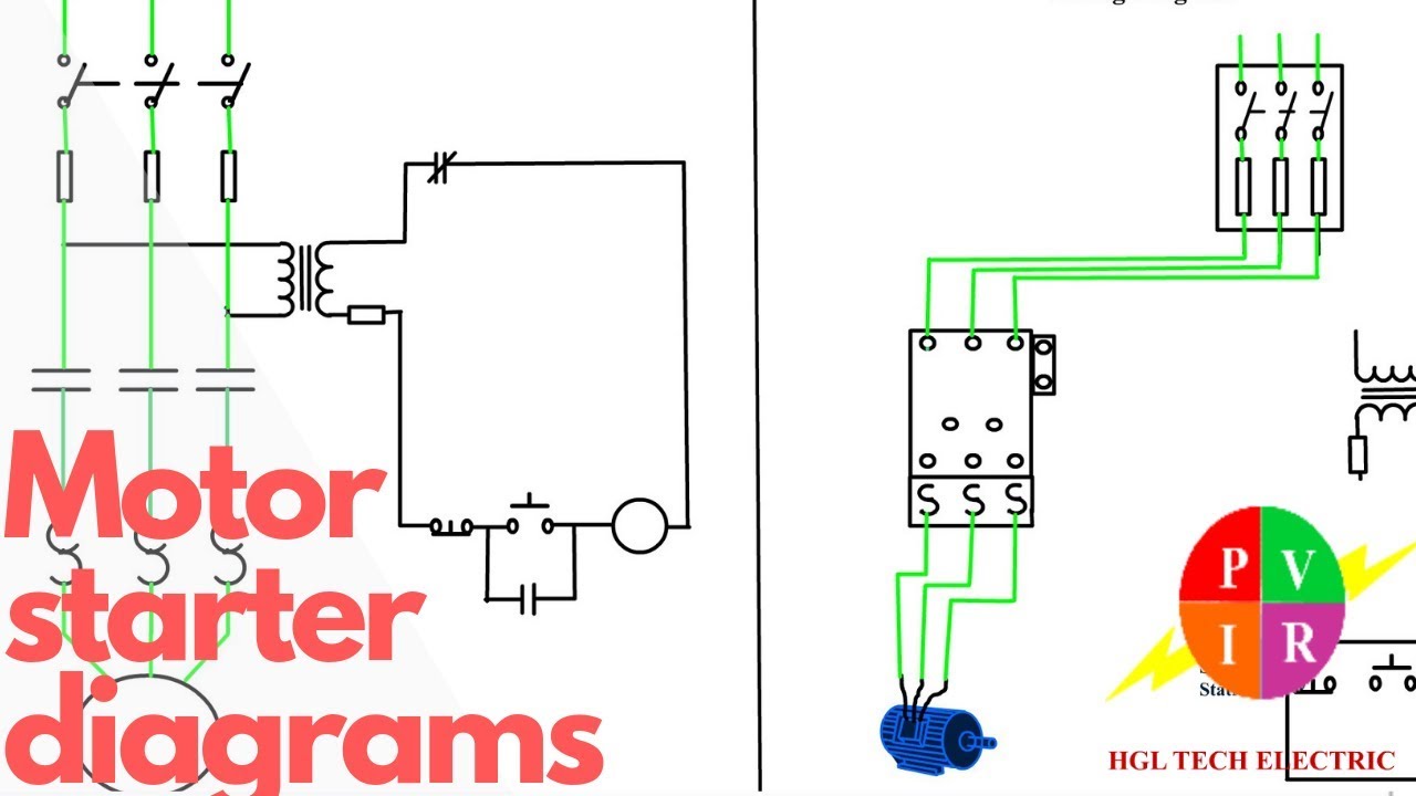
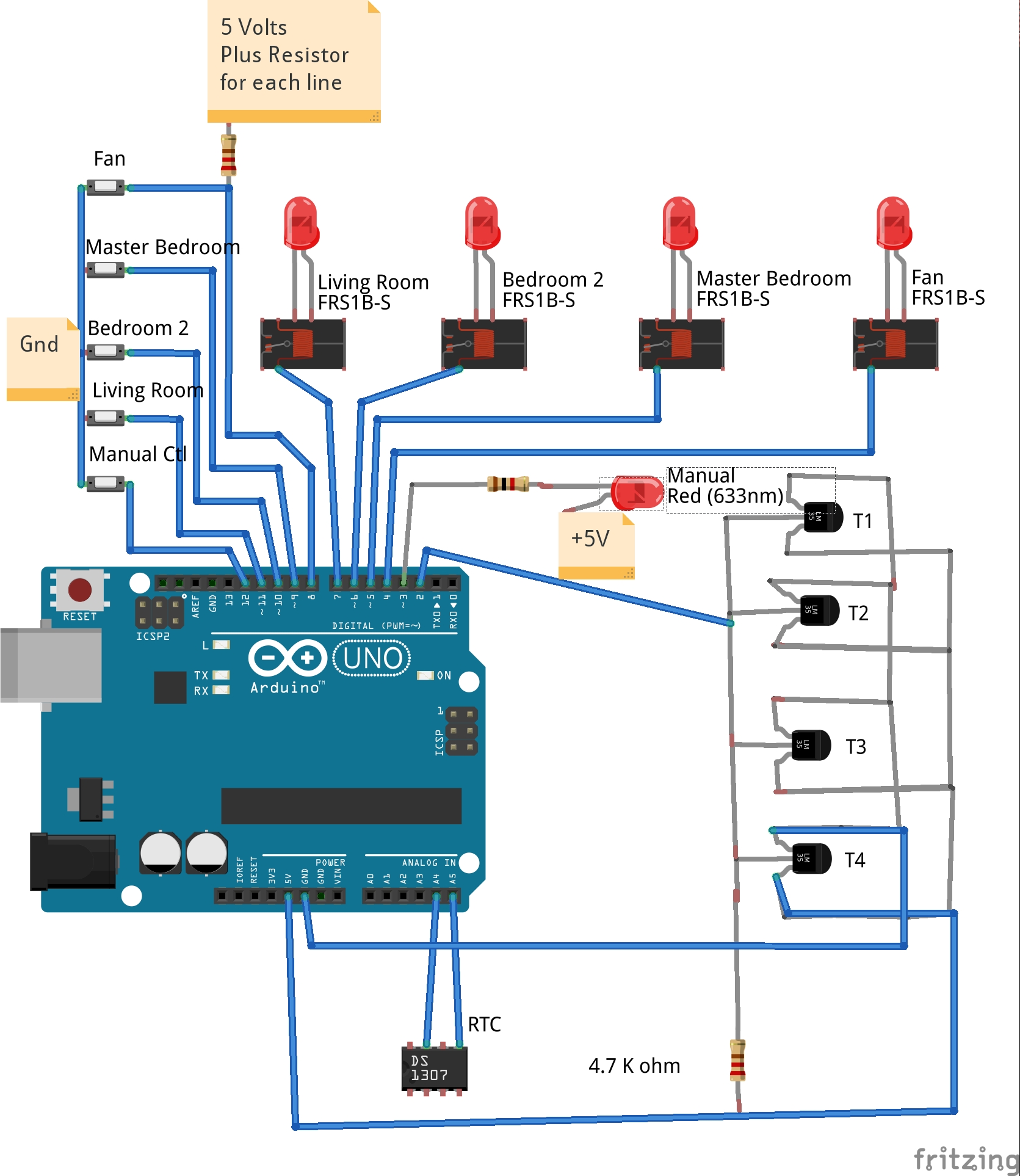
Jet fan control wiring diagram. Pick the diagram that is most like the scenario you are in and see if you can wire up your fan. 18 gauge standard single thermostat standard ac condenser ac contactor control board standard air handler 3 this diagram is to be used as reference for the low voltage control wiring of your heating and ac system. 3ø wiring diagrams 1ø wiring diagrams diagram er9 m 3 1 5 9 3 7 11 low speed high speed u1 v1 w1 w2 u2 v2 tk tk thermal overloads two speed stardelta motor switch m 3 0 10v 20v 415v ac 4 20ma outp uts diagram ic2 m 1 240v ac 0 10v outp ut diagram ic3 m 1 0 10v 4 20ma 240v ac outp uts these diagrams are current at the time of publication. 801x lect 24 rolling motion gyroscopes very non intuitive duration. To wire a 3 way switch circuit that controls both the fan and the light use this diagram. With these diagrams below it will take the guess work out.
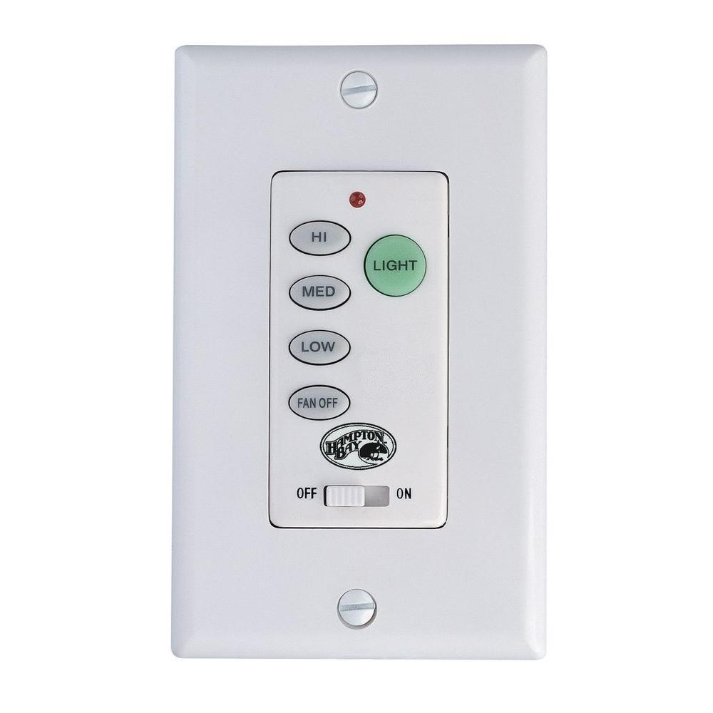
Control wiring wire size. This might seem intimidating but it does not have to be. Ceiling fan wiring diagram. 3 way fan switch wiring diagram. Always refer to your thermostat or equipment installation guides to verify proper wiring. Lectures by walter lewin.
Fault finding 9 91 electrical 9 92 mechanical 9 10. Fan power and ground. Suggested electric fan wiring diagrams page 1 these diagrams show the use of relays onoff sensors onoff switches and onoff fan controllers. 52 fuses wiring 5 53 speed control 5 54 overheat protection 5 55 emergency use fans 6 56 switch on 6 60 maintenance 7 70 infrequent use 7 80 overhaul extended maintenance 9 9. As with all 3 way circuits the common on one switch is connected to the hot source wire from the circuit. They will make you physics.
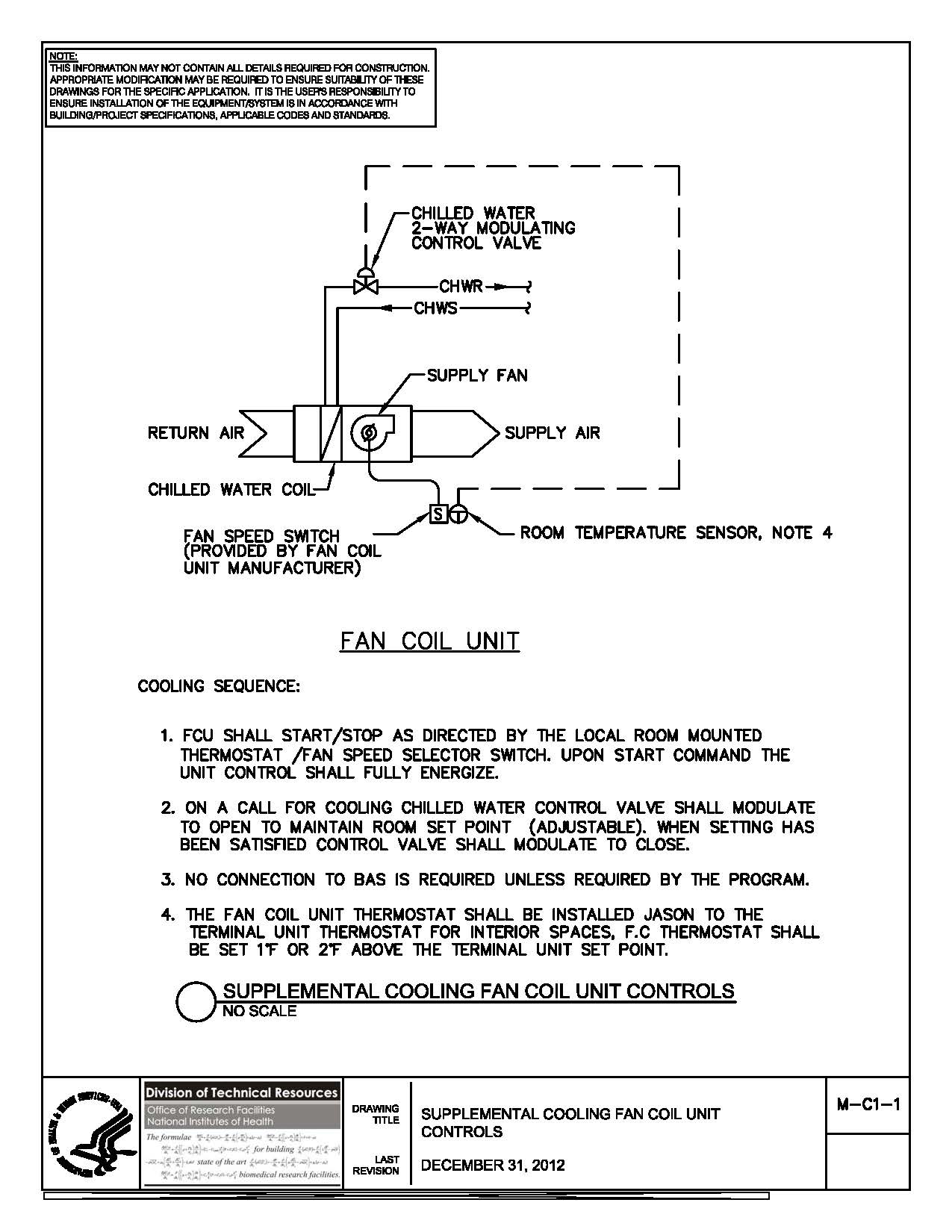
Disposal 9 110 connection diagrams 10. Fan control this incorporates the current and voltage supply for the entire system as well as the load control and logic units of the main and jet fans via a contactor circuit or optionally via a frequency converter. The circuit is also equipped with fail safe hard wiring but can also be implemented with a plc programmable logic. Take a closer look at a ceiling fan wiring diagram.
Gallery of Jet Fan Control Wiring Diagram
.png)