Apfc stands for auto power factor correction panel. Wiring diagram of apfc panel images 375 part of wiring diagram free save your favourite image or wallpapers.
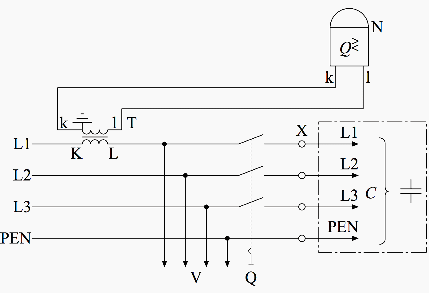
Wiring Of Power Factor Relay On Lv And Mv Side Circuit
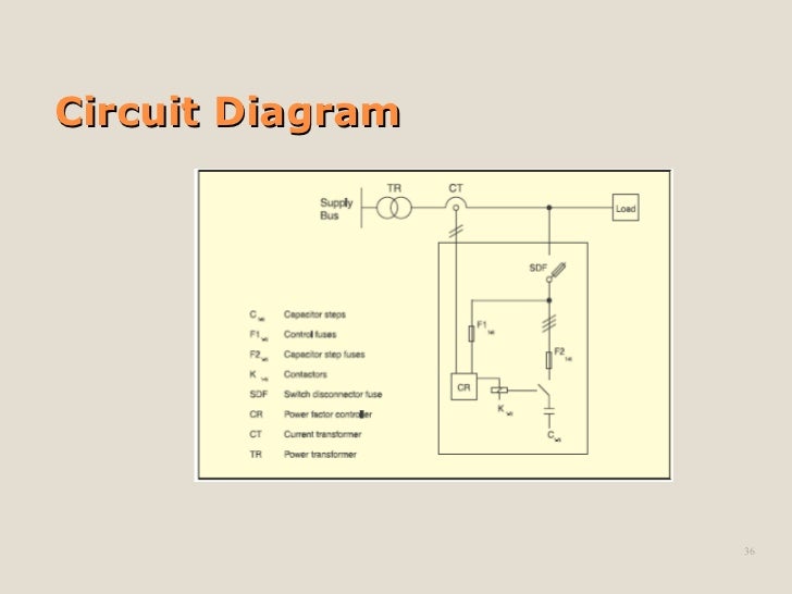
Apfc panel wiring diagram. In case there is no transformer in the installation then the ct for sensing power factor should be provided at the incoming of main switch of the plant. 1 200 kvar apfc panel 12 stage 200 kvar apfc panel rhom lt d sine 2 spredor link lt d sine 2 cap duty contactor lt moc 2 add on lt moc 2 on delay timer giceq 18 sec 2 lum pb tekniceq lpbo 4 capacitor bank 440vac 50 hzs mpph 10 kvar ltepcos mpph 20 e 5 kvar capacitor feeder 5 kvar 2 32a tp mccb 25 ka with tmd release lt d sine 2. That photograph apfc relay control wiring diagram apfc panel wiring diagram pdf within relay panel. Pfi panel board wiring diagram power factor improvement diagram pfi circuit diagram apfc fig duration. Review again 2255 views. 16 tida 00737 this ti design demonstrates the working of various blocks that are typically used in the apfc in an optimized way with flexibility to expand.
The apfc panel has a number of capacitor banks and busbars that carry large currents. It is used to improve power factor to meet the current requirement to reduce the billing and also to improve feeder voltage regulation. Apfc panel control wiring diagram how to do control wiring of auto power factor correction panel duration. Through the thousands of pictures on the web about relay panel wiring diagram we choices the top libraries using best quality simply for you all and now this images is actually one of images choices in your best photos gallery regarding relay panel wiring diagrami really hope you may want it. Note that apfc panel can maintain the power factor on lt side of transformer and it is necessary to provide fix compensation for power transformer refer fig no 1 5. Electrical infinity 6351 views.
Refer fig no 3 figm. Exhaust fans are used to maintain the temperature of the apfc panel.
Gallery of Apfc Panel Wiring Diagram