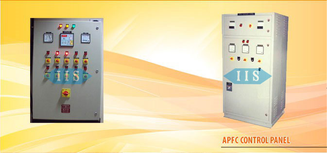
We manufacture a wide range of these panels. Apfc panel wiring diagram pdf download read online.

Manual For Apfc Panels Installation And Commissioning Pdf
Thyristor based apfc panel wiring diagram. We are the only panel manufacturer who provides distribution pdf. Download apfc panel wiring diagram pdf free files. During the positive half cycle of the sinusoidal waveform the device is forward biased but with switch s 1 open zero gate current is applied to the thyristor and it remains. The above thyristor firing circuit is similar in design to the dc scr circuit except for the omission of an additional off switch and the inclusion of diode d 1 which prevents reverse bias being applied to the gate. Exhaust fans are used to maintain the temperature of the apfc panel. Apfc stands for auto power factor correction panel.
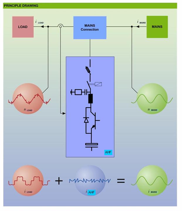
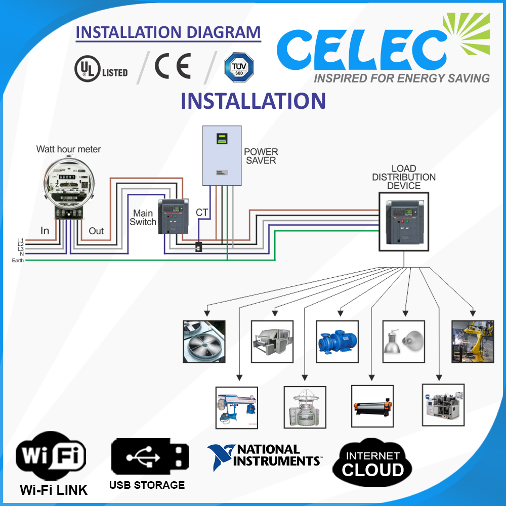
Auxiliary power supply. Capacitor switching at precise zero current crossover threshold means. Thyristor control panels are basically used to control voltage and monitor the working of heaters and variable applications in a production line. Apfc electrical thyristor apfc panel control wiring diagram apfc panel control wiring diagram in hindi apfc panel working in hindi apfc panel testing thyristor based apfc panel wiring. Fast acting thyristor switched automatic harmonic filter panel rtpfc panel is real time passive tuned filter systems using clariant make thyristor switched modules. Note that apfc panel can maintain the power factor on lt side of transformer and it is necessary to provide fix compensation for power transformer refer fig no 1 5.
That photograph apfc relay control wiring diagram apfc panel wiring diagram pdf within relay panel. The apfc panel will have an auxiliary power supply that powers its various functional blocks. Through the thousands of pictures on the web about relay panel wiring diagram we choices the top libraries using best quality simply for you all and now this images is actually one of images choices in your best photos gallery regarding relay panel wiring diagrami really hope you may want it. Refer fig no 3 figm. 21 circuit diagram of 3 ø system figure 4. No inrush current at switching no instant no generation of voltage or current spiker.
Voltage across the thyristor is zero. In case there is no transformer in the installation then the ct for sensing power factor should be provided at the incoming of main switch of the plant. Block diagram of 3 ø system this figure 4 seems that power circuit diagram of rtpfc panel. It consist of high grade thyristor with fuses mcbs and mccbs heaters contactors isolation switches indication lamps alarm system etc. The apfc panel has a number of capacitor banks and busbars that carry large currents. Thyristor switched capacitor banks dynacomp low voltage pdf.
3bab4 apfc control wiring diagram wiring library pdf. This control circuit will control the load power factor by sensing various parameters like switching devise thyristor inductors capacitor banks etc. It is used to improve power factor to meet the current requirement to reduce the billing and also to improve feeder voltage regulation.
Gallery of Thyristor Based Apfc Panel Wiring Diagram