To enter the calibration setup mode make sure the meter is powered off. Wiring representations are made up of 2 points.

Gm Voltmeter Wiring Diagram Wiring Ammeter And Voltmeter
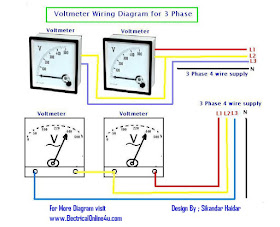
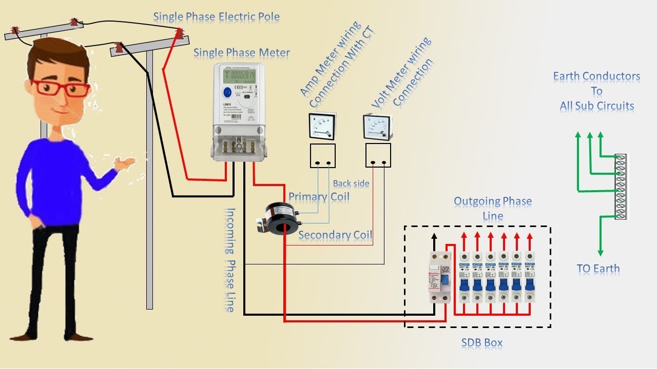
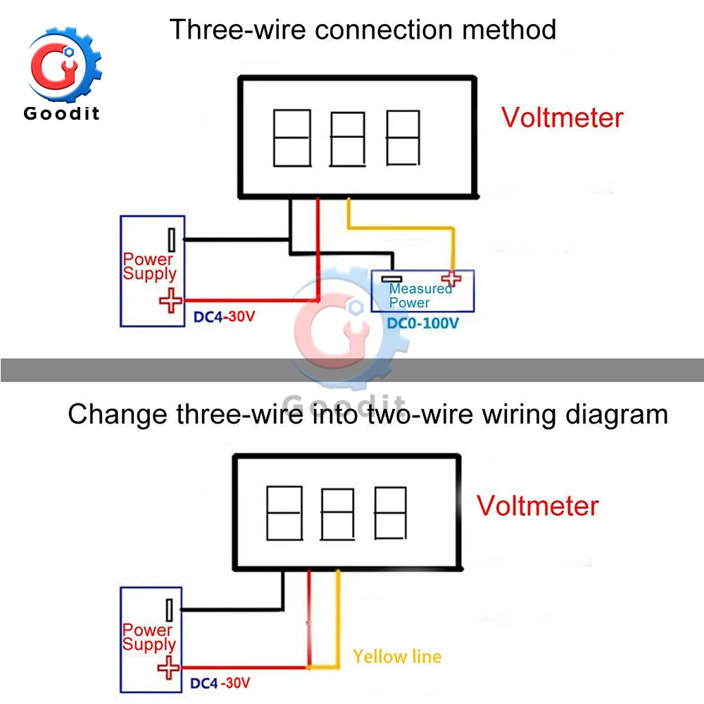
Voltmeter wiring diagram. The voltmeter connection can be made at the battery positive and negative if desired. Dc voltmeter mainly consists of a dc amplifier apart from the attenuator as shown in figure. Connect the end coming from the steering column to the voltmeter. In above voltmeter wiring diagram i shown the a voltmeter with electric supply and as i wire the voltmeter same you can wire and do it same just like i shown in above diagram how ever soon i will upload practical example which will help you very much. Take the negative wire from the voltmeter and make a good connection on a grounded screw in the car. The voltmeter ammeter can be easlily calibrated by temporaily connecting three setup up down tactile buttons or even a piece of wire to c1 c2 and c3 pic16f876 microcontroller ports.
Dc voltmeters can further be divided into two categories. Dc voltmeter block diagram. Voltmeter gauge wiring diagram wiring diagram is a simplified customary pictorial representation of an electrical circuit. Direct coupled amplifier dc voltmeter. The wire from the fuse box step 3 should. In above voltmeter wiring diagram i shown the voltmeter symbol which can help you in incoming articles.
This type of voltmeter is very common because of its low cost. A wiring diagram is a type of schematic which utilizes abstract pictorial signs to show all the affiliations of elements in a system. Dc voltmeter block diagram. Step 6 connect positive wire. It shows the components of the circuit as simplified shapes and the facility and signal contacts with the devices. Use one of the wires that you found in the wiring harness and cut it between the steering column and connector in the dash.
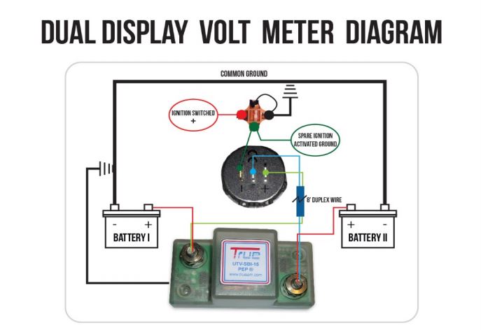
Voltmeter instructions wire nut flat washer nut washer voltmeter grommet u bracket do not leave any hardware out of these connections diagram 1 ground source step 2 should be connected as shown in diagram 1 to the voltmeters connection post marked. Butt connectors are stronger and more reliable but wire taps are faster and dont require cutting the original wire. Use either butt connectors or the commonly supplied wire taps to connect the voltmeter wires to the wiring harness. Wiring diagram voltmeter car new digital volt amp meter wiring ammeter shunt wiring diagram new digital volt amp meter wiring whats wiring diagram.
Gallery of Voltmeter Wiring Diagram