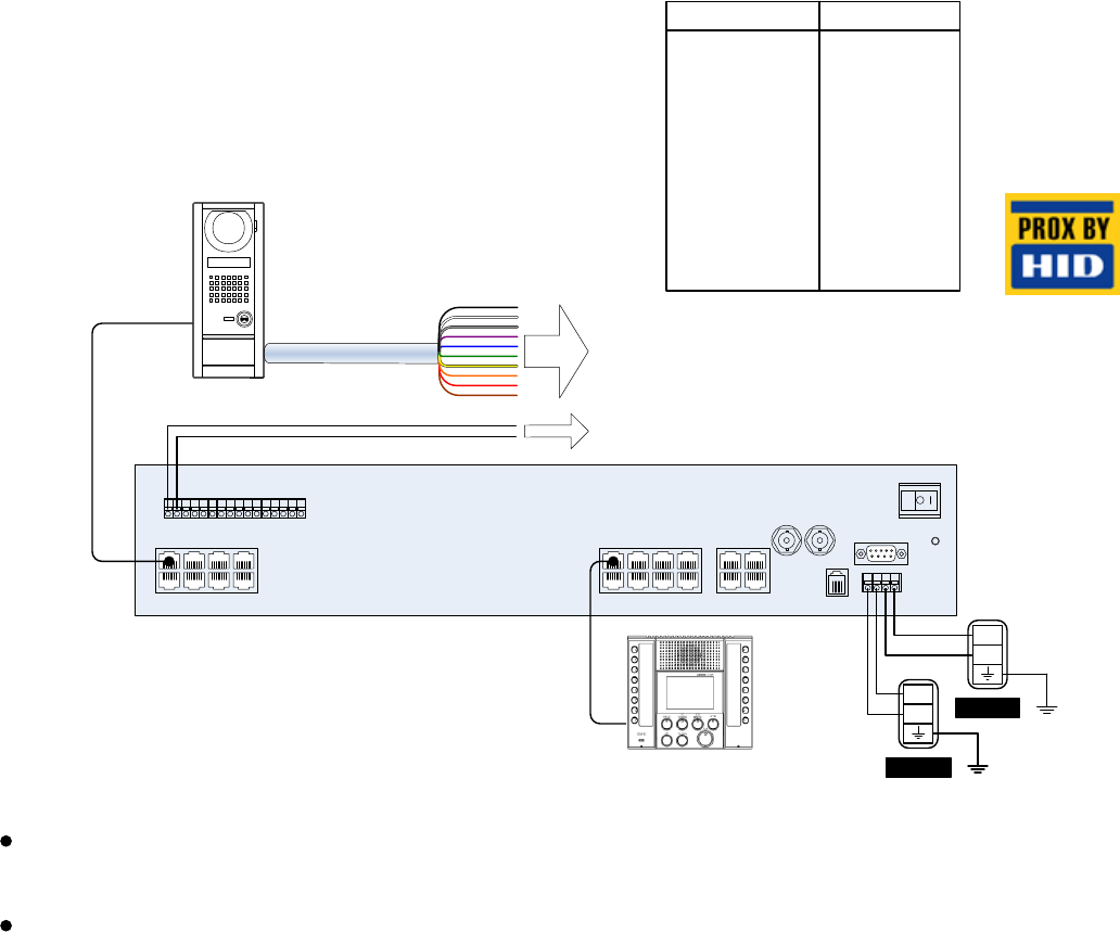
Tenant stations gt vbc k ke ry ry sw sw s1 s1e s2 s2e s3 s3e brn emergency alarm red blu ext. Signaling gt ry wht.

Va 4843 Aiphone Intercom Wiring Diagram And Installation
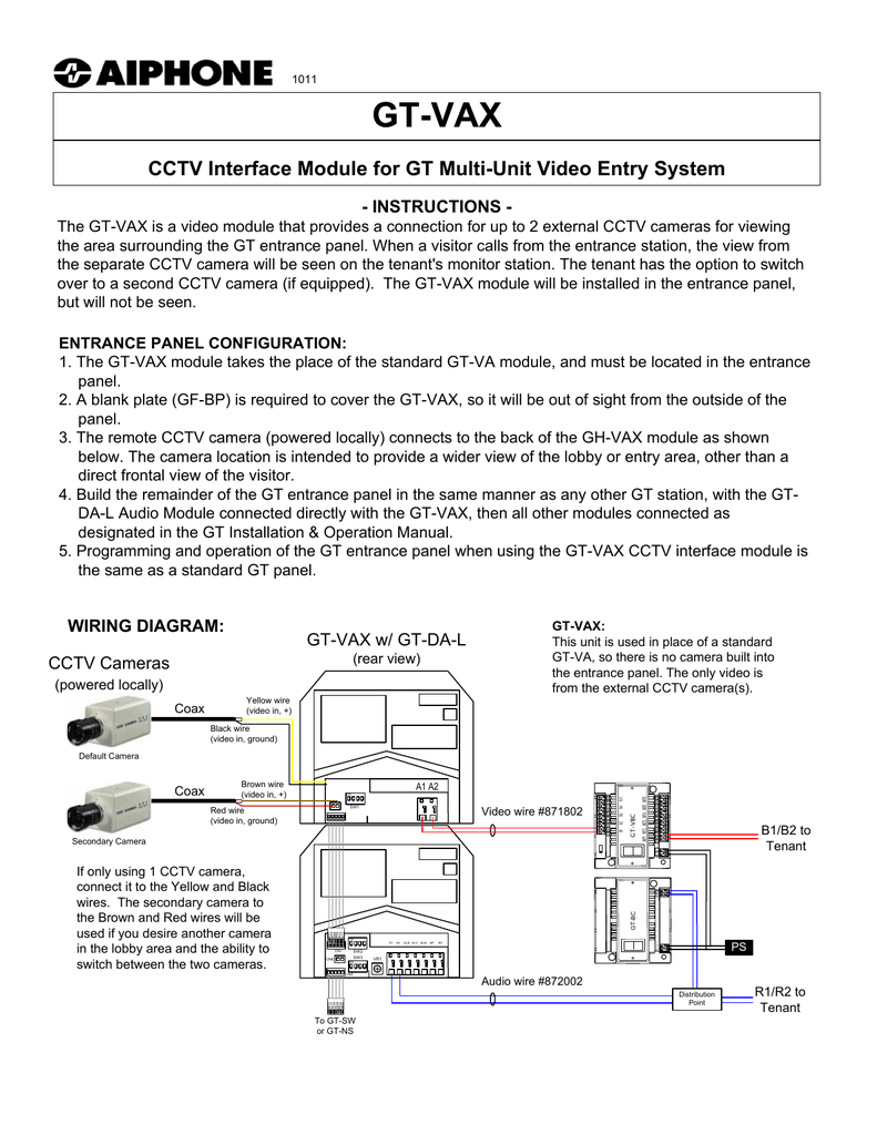
Aiphone gt wiring diagram. If gt db v or gt db vn is used in an entrance. Aiphone gt system block wiring diagram distributed by. For power supply use aiphone power supply model or model specified for use with system. Page 7 video door station or doorbell gt 2c l gt 2c gt d sub master monitor station aiphone jf dvf gt 2h l gt 2h ps24 power supply related when sub master monitor stations are connected if even just one sub master monitor station is connected it is possible to supply power to up to 2 residences with 1 power supply. Gt vb gt db v vn expanded system wiring option connector wiring. If non specified product is used fire or malfunction could result.
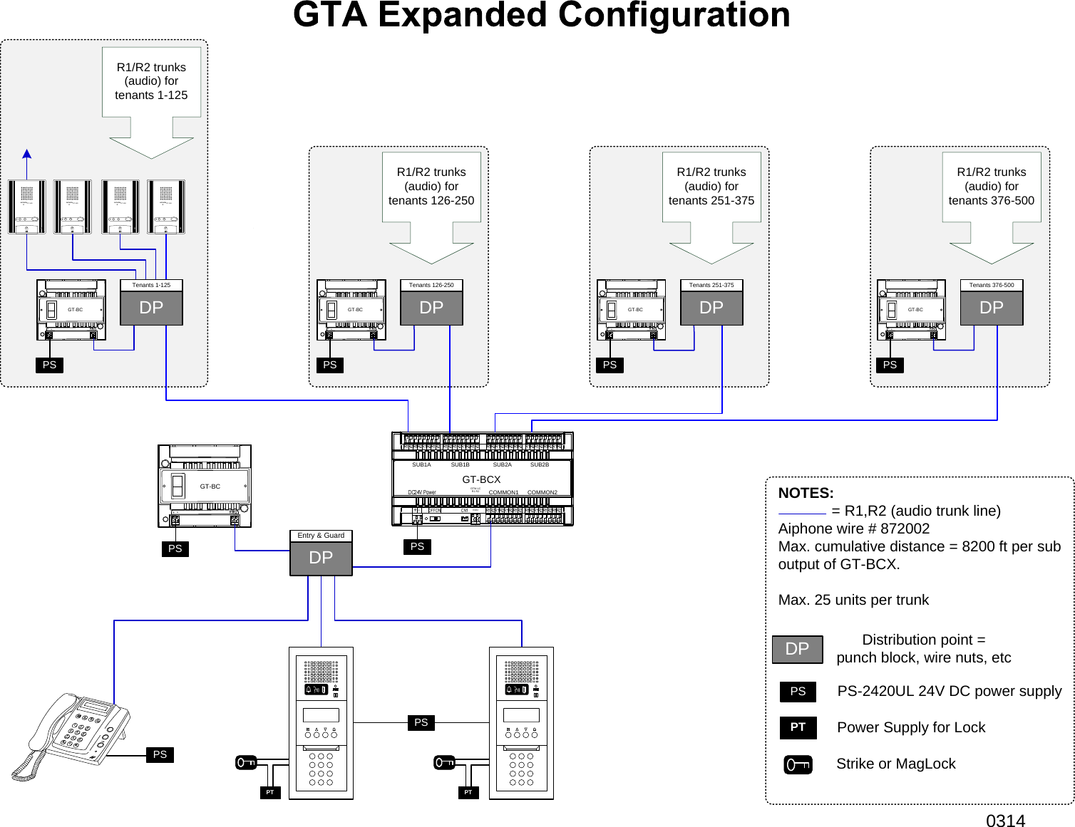
If gt db v gt db vn or an external door release button is connected to an entrance station that includes gt sw a maximum of 3 entrance stations can be connected to the system. Up to 3 entrance stations can be connected per audio signal line from the dp. It reveals the components of the circuit as streamlined shapes as well as the power as well as signal links between the gadgets. Gt series multi tenant entry security. 2 the maximum is 100 stations with the gt 1d and gt 1m l only. Maximum 50 stations per trunk.
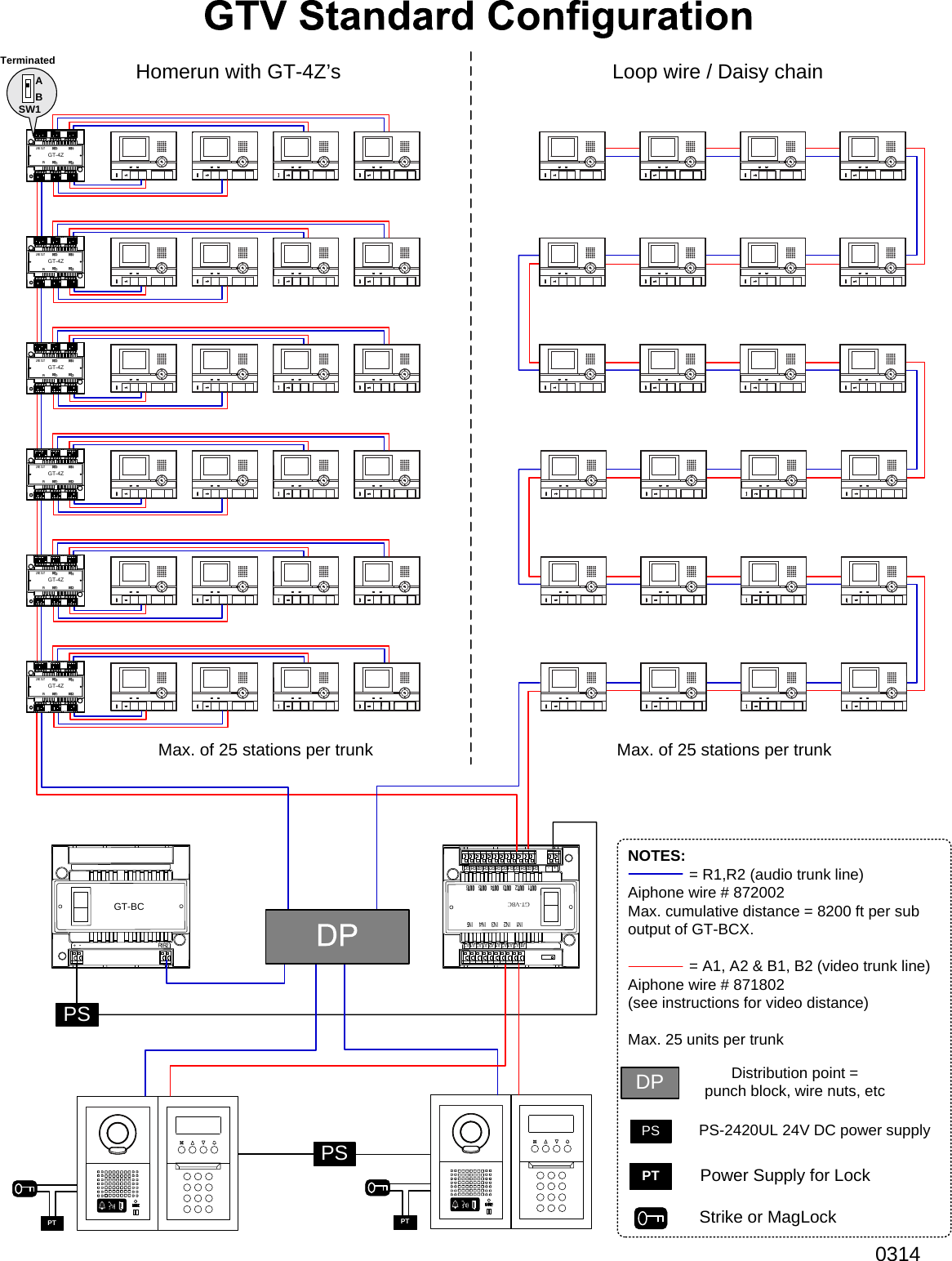
8 two communication paths sub 1 sub 2 common 1 common 2 one communication path sub 1 sub 2 common 1 common 2 1p 1px2 1px2 1p gt 1c gt 2c gh 1md doorbell doorbell jk dv or gt 1c gt 2c gh 1md gh 1kd doorbell doorbell jk dv. A wiring diagram is a simplified conventional pictorial representation of an electrical circuit. 1 2 expanded system configuration diagram the wiring of the sub trunk. Assortment of aiphone intercom wiring diagram.
Gallery of Aiphone Gt Wiring Diagram
.jpg)