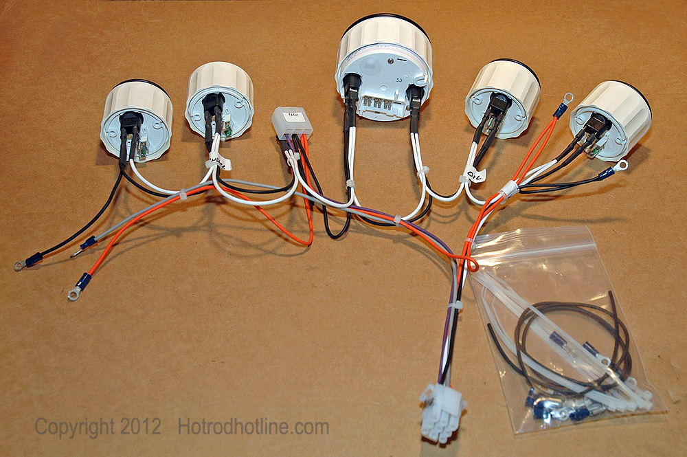
Autometer or vdo electric speedometer sensor allows use of a sandrail dune buggy manx rock crawler volksrod or mud buggy vw parts. Junction and attach the wire from the speedometer.

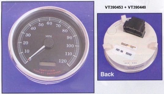
356 Gauges 356 120mph 100mm Speedometer Speedometer By
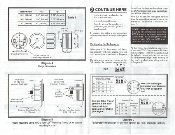
Vdo speedometer wiring diagram. Only connect cables according to the electrical wiring diagram. Refer to diagram d for the proper wiring of the speedometer. Lamp socket push in wedge type 2 3. Vdo wiring diagrams diagram will open in a new window. Light bulb 12 volt ge. Grammable speedometer included in this kit has a special set of in stallation and operation instructions.
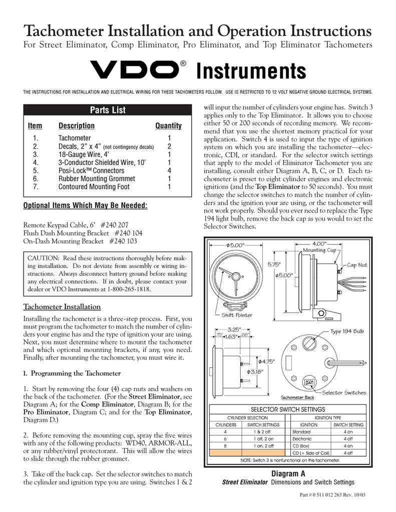
Diagram a vdo tachometer with hourmeter is programmable from 5 to 200 pulses per revolution vdo vdo item description quantity 1. 161 or equivalent 2 4. Vdo spin lok mounting clamp 1 5. Assembly or wiring instructions. Lamp socket push in wedge type 2 3. Drive a known course with a distance of up to 10 miles.
0 electronic speedometer hall effect sender installation instructions and wiring diagram 7udqvplvvlrq type a speedometer 4 wire system 57. Mph kmh. Light bulb 12 volt ge. These instructions must be followed carefully to insure proper performance of the speedometer. Finally there is a method which uses the speedometers trip odometer as a pulse counter. Fuel voltmeter electric speedometer or tachometer w odometerrev counter alternator.
Wire the gps speed sender as follows wire color function red 12v black ground green signal output to speedometer white signal switching to ground 12vfor 200000 pulses to power 12v for 16000 pulses use 200000 pulses when using a vdo speedometer. Installationoperation instructions 1 ˇ ˆ ˆ ˆˆ ˆ ˆ ˆ. Be sure the speedometer pointer does not exceed the maximum speed of the speedometer. 158 or equivalent 2 4. Install and wire the speedometer as shown earlier. Diagram a proper mounting using vdos spin lok mounting clamp minimum mounting depth 2 78 73mm speedometer installation.
Use 16000 pulses for most non vdo speedometers. Always disconnect the battery ground before making any electrical connections. Set all dip switches to the on 1 position.
Gallery of Vdo Speedometer Wiring Diagram