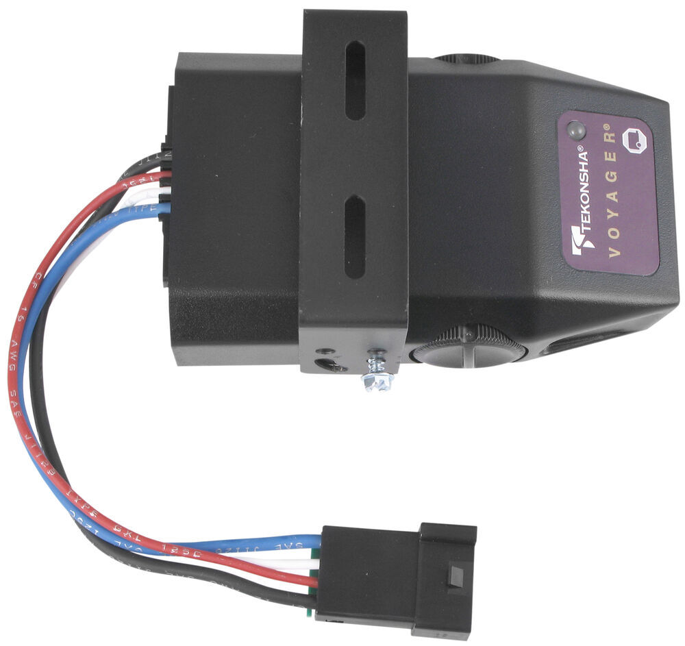
It is compact size and features like a bicolored led brake monitor to assure a complete connection to trailer brakes and give an indication of relative braking power being applied make the voyager extremely versatile. Tekonsha brake controller wiring diagram wiring diagram for trailer brake controller best tekonsha voyager wiring diagram for trailer brake controller 9030.
Billavista Com Trailer Brake Controller Tech Article By
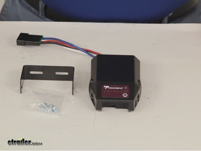
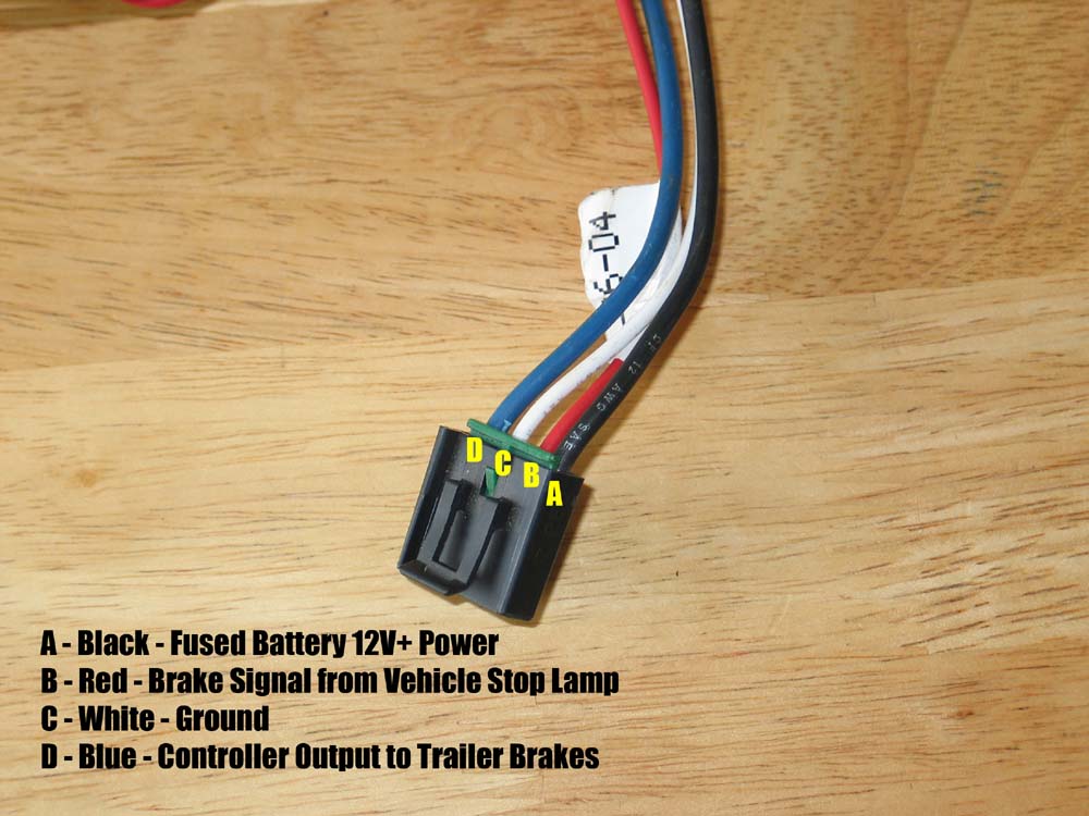
Tekonsha voyager brake controller wiring diagram. The problem i have is there are 5 wires on the wiring harness and only 4 on the controller. You will want to make sure that you ground the white wire to the negative post on the battery. Important facts to remember. The black wire will attach to the positive battery post. For 2 4 6 and 8 brake applications. Bracket mounting holes d.
Tekonsha the tekonsha logo and tekonsha graphics are the servicemarks trademarks or registered trademarks owned by horizon global corporation. Do not mount or activate rf generating items cell phones two way radios near less than 12 the brake control. I have a 2006 chevy suburban equipted w a trailer package i have the wiring harness to install on to my tekonsha voyager brake controller. The voyager incorporates patented braking sensor by tekonsha and is the best value you will find for smooth and secure trailer braking. Assortment of tekonsha voyager wiring diagram. Collection of tekonsha brake controller wiring diagram.
Tekonsha voyager 9030 minimizes interference with tow vehicle electrical systems uses a four wire hook up has a broad setting range and is compatible with most any vehicle. A wiring diagram is a streamlined standard pictorial depiction of an electrical circuit. This tekonsha trailer brake controller wiring diagram model is much more suitable for sophisticated trailers and rvs. White pin to your floor. It may transfer power better hence the connector is suggested for higher level electric in the auto. Tekonsha voyager trailer brake controller not.
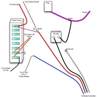
Components of the brake control. The red wire will tap into the stoplight switch on your vehicles brake pedal. It shows the parts of the circuit as simplified shapes and the power and signal links in between the gadgets. I have attached a basic brake controller wiring diagram for you. All other servicemarks and trademarks are the property of their respective owner. Here is the diagram for 7 pin connector.
Gallery of Tekonsha Voyager Brake Controller Wiring Diagram