Each part should be placed and connected with other parts in particular way. Typical wiring diagrams for push button control stations 7 start stop control wiring diagrams single station with motor stopped pilot light l1 start l2 i 1 stop 2 oi 3 n wol.

Why You Should Use Normally Closed For Stop Buttons
Stop start switch wiring diagram. Hello every one how to connection stop start with mini plc in circuit. Single station with the starter. The guide incorporates a great deal. Electric parts needed for the wiring above. Tor thermal overload relay 28a. Start stop control wiring diagrams.
C i m nc. 1 magnetic contactor 220vac. It includes guidelines and diagrams for various types of wiring techniques along with other products like lights windows and so forth. Three wire control multiple stations start stop switch wiring diagram. A quick video on how to wire an nvr switch no volt release switch with an emergency stop e stop. If in any doubt consult a suitably qualified electrician.
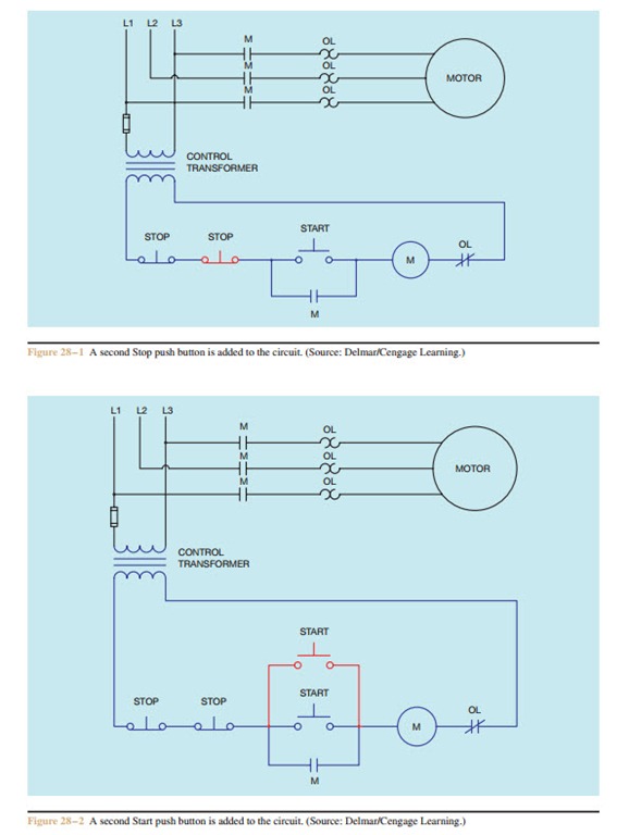
Wiring diagram single motor with start stop switch. Pilot light l2 4 2 3 pilot light start stop bulletin 1495 normally closed auxiliary contacts are required. Video intended as a guide only. How to wire contactor and motor protection switch direct on line. M1 motor 15kw 380v 3phase. In this video you can onoff device by switching the first click on switch device is active the second click on switch.
Otherwise the structure wont function as it ought to be. S1 push button switch ptb non latching stop switch. Start stop push button wiring diagram emergency stop push button wiring diagram start stop push button station wiring diagram start stop push button switch wiring diagram every electrical structure consists of various different parts. B1 mcb 5a 3 phase. See image below for an example of 3 wire control being used to pull in a contactor to start a 3 phase motor. T w 6.
When you press the start button and the stop button. Wiring diagram consists of numerous detailed illustrations that display the link of varied things.
Gallery of Stop Start Switch Wiring Diagram