Safety note always disconnect the vehicle battery while installing this or any other automotive electronic product. The gnx 3 is an ideal solution for mobile resource management vehicle tracking and many other location aware applications and services.

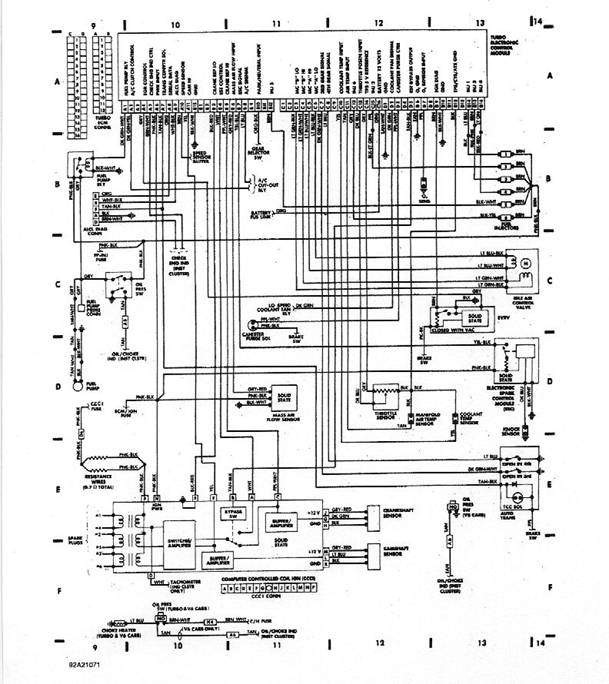
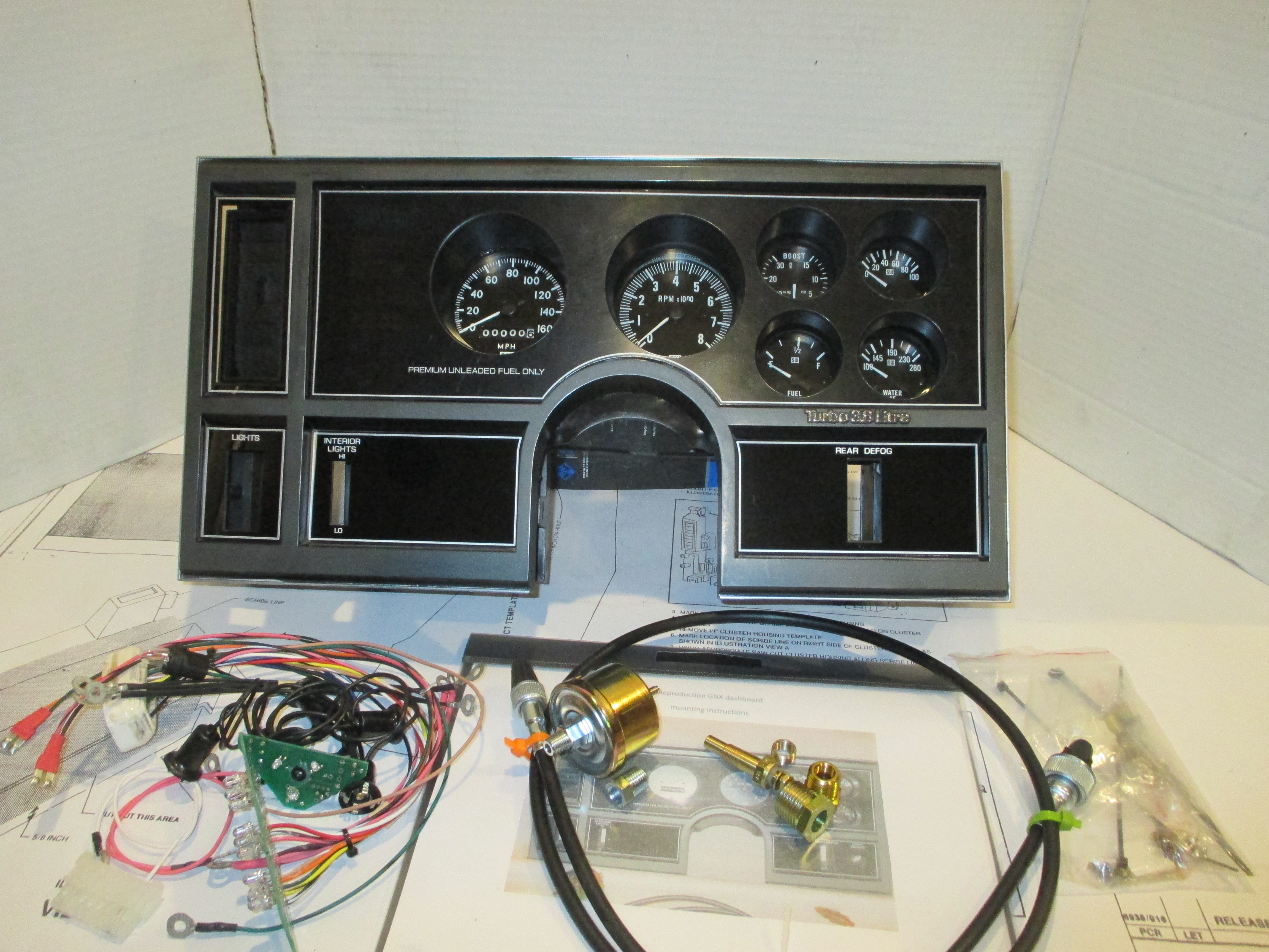
Instrument Cluster Wiring Diagram Schematic Buick Gnx Dash
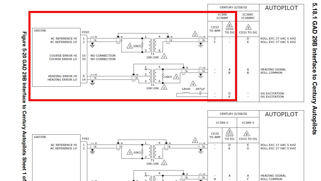
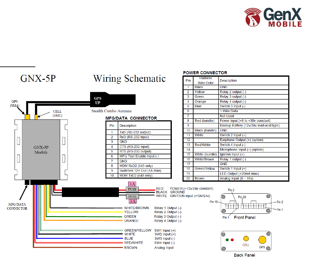
Gnx 3 wiring diagram. Fleet tracking with wireless communications canbus eco accelerometer internal battery ibutton 1 wire. Yellow greenh whitebrovun fleet tracking e take charge of your fleet. The green led will show solid for approximately 30 seconds. At no other time should the green led remain on solid for. Relay 1 output bundle white. Page 3 of 11 dq technologies inc phone.
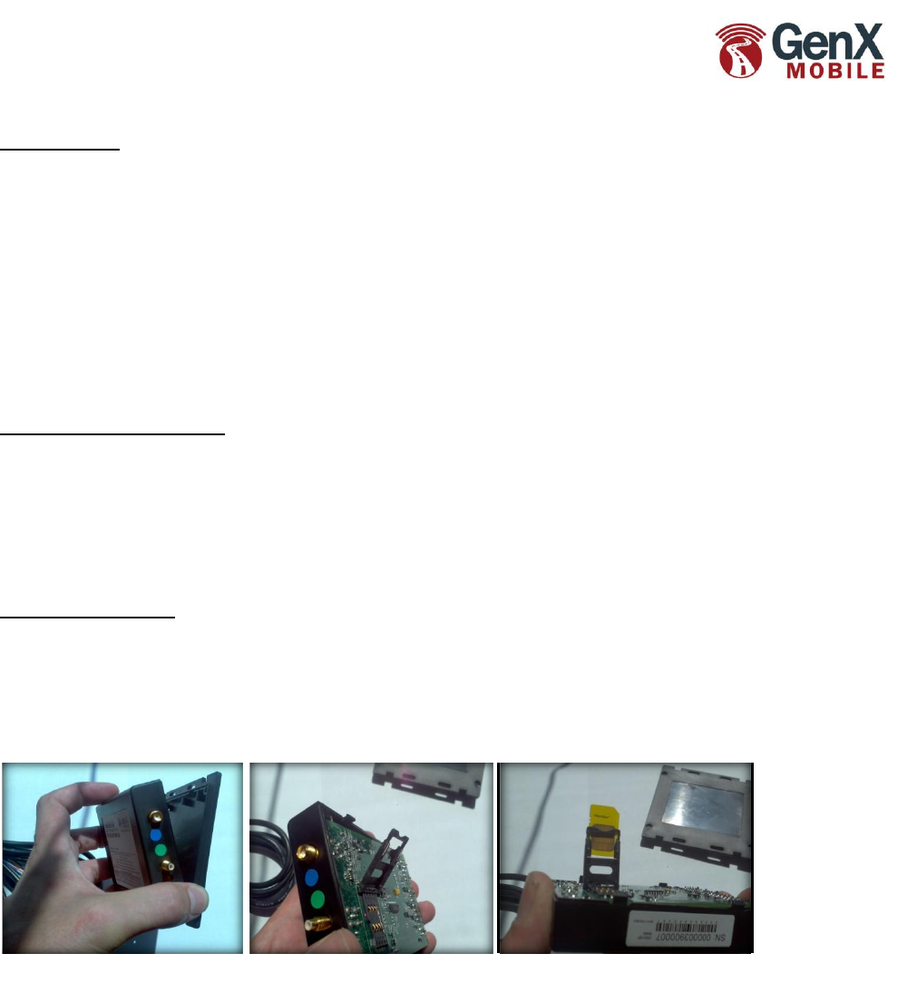
3 wire power cable standard dq technologies install only the 3 bundled wires on the long black cord with the 3amp in line fuse red black and white need to be connected. Relay plugs into wiring harness they do come apart white lines next to numbers in above diagram represent the orientation of the contacts that connect the relay to the wiring harness see pg. Gps genx installation guide. Fleet tracking with low energy bluetooth and canj17081939 technology canbus obdii eco accelerometer internal battery ibutton 1 wire. Gnx 3 module i able side skyward back of gnx3 pin 18 power connector pin 17 pin 2 pin 1 ground ignition 12v24v ground reiss 2 output as p t o in swi input as p muc in the app. Wiring schematic diagram11.
When the ignition is first turned on the gnx will power up. 2 for photos yellow wire from gnx is the only wire pertinent to the starter interrupt install. For purpose of starter interrupt. The gnx 3 is a highly configurable feature rich mobile asset tracking device designed to service a wide variety of market and industry requirements.
Gallery of Gnx 3 Wiring Diagram