Car fuse box diagrams. Traffic signal stop light wiring with arduino controller.

Puch Wiring Moped Wiki
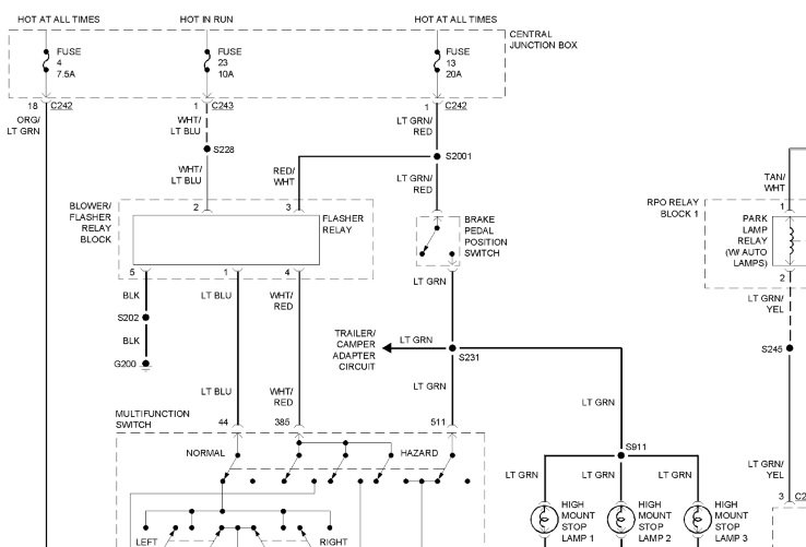
Stop light wiring diagram. What fun is that. A wiring diagram is a streamlined conventional photographic representation of an electric circuit. I also wanted to try out an arduino controller and thought this would be a nice simple. Collection of start stop wiring diagram. 1992 chevrolet nova fuse box diagram. It shows the parts of the circuit as simplified forms and also the power and also signal links in between the devices.
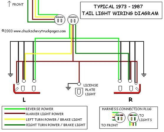
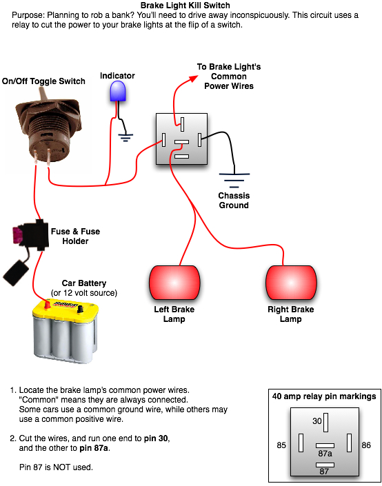
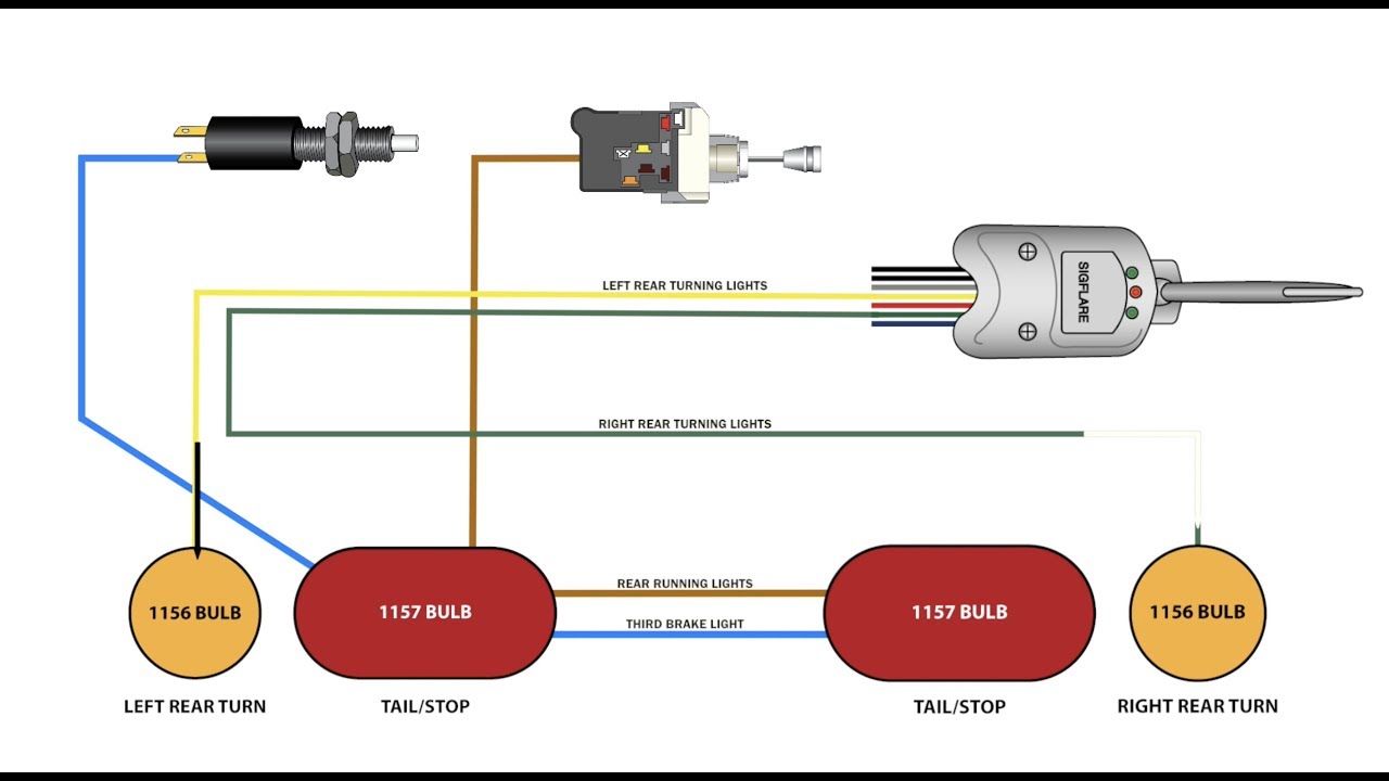
Variety of universal turn signal wiring diagram. The source is at sw1 and 2 wire cable runs from there to the fixtures. However it was very simply wired so that all the lights were fixed on. I always wanted an old traffic signal and finally got one recently. Visit howstuffworks to check out this brake light wiring diagram. Relay schematic circuit schematic diagram schematic diagrams starter relay studebaker wiring wiring connection wiring diagram wiring diagrams wiring harnes wiring schematic wiring system wiring work.
Multiple light wiring diagram. The hot and neutral terminals on each fixture are spliced with a pigtail to the circuit wires which then continue on to the next light. It reveals the components of the circuit as streamlined shapes as well as the power as well as signal links in between the gadgets. This diagram illustrates wiring for one switch to control 2 or more lights. A wiring diagram is a streamlined standard pictorial depiction of an electric circuit. Brake light wiring diagram this brake light wiring diagram gives you a clear picture of where each wire goes.
Gallery of Stop Light Wiring Diagram