External installation mount cpu to a surface using double sided tape or fasten using a screw. Switched signal nc black.

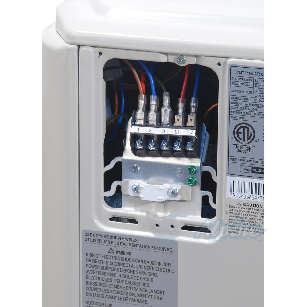
Air Conditioning Unit Air Conditioning Unit Voltage
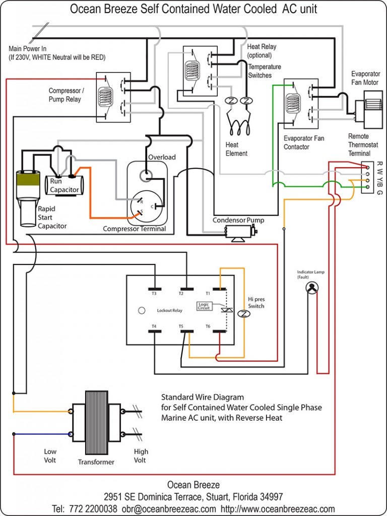
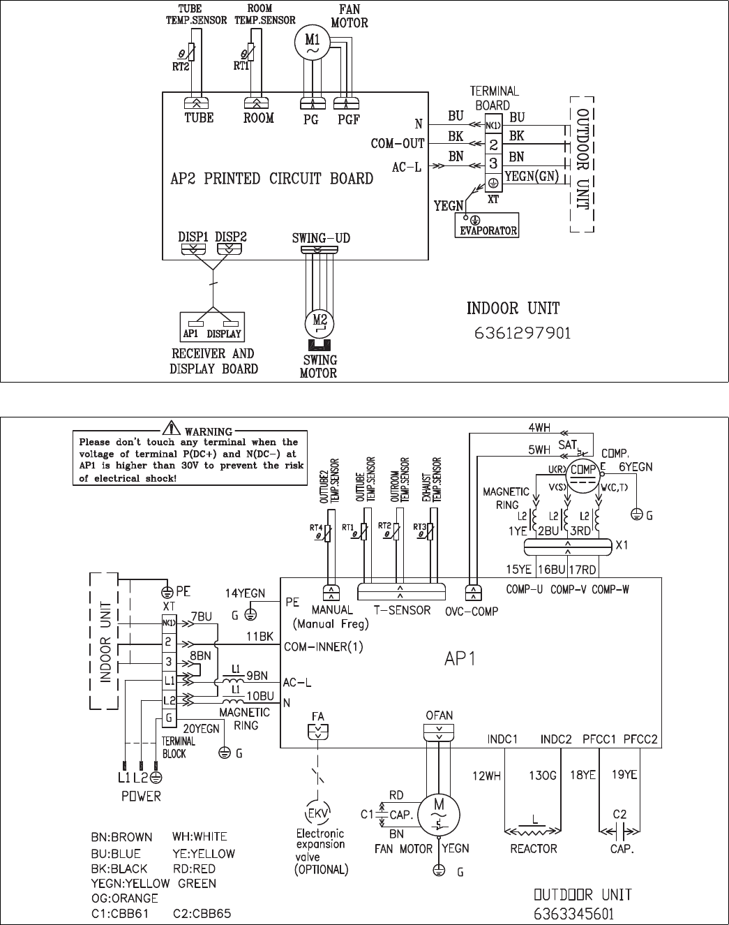
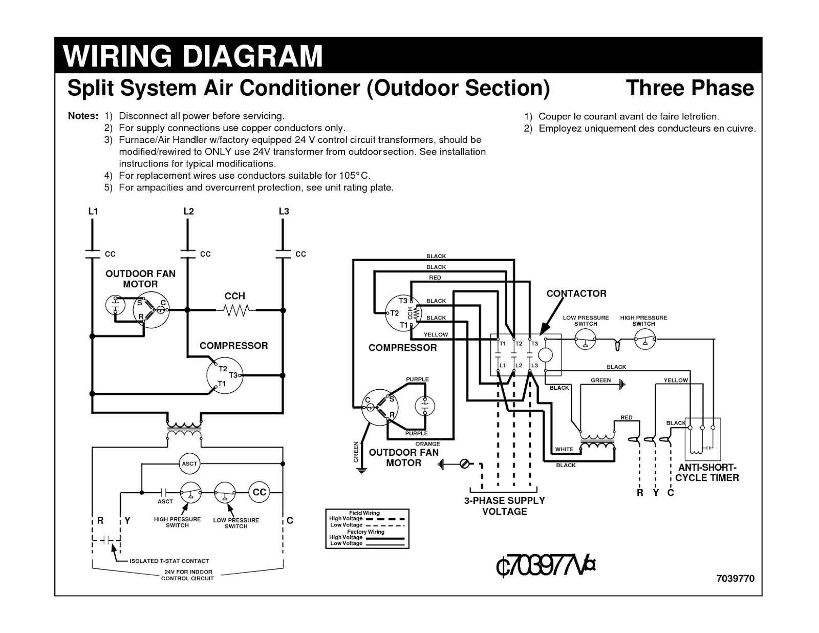
Ss610e wiring diagram. Assortment of chevrolet s10 wiring diagram. Please refer to air conditioners manuals for correct wiring terminal layout and wiring instructions. Its small sensor can easily fit in the confined internal spaces of most units. Wiring diagram for fujitsu ductless minisplit system fitted with ss610e electronic overflow condensate switch rev a 102012 1. Its small sensor can easily fit in the confined internal spaces of most units. Safe t switch ss610e is specially designed for use in mini split systems.
Rectorseal 97622 safe t switch model ss610e ss610e is specially designed for use in mini split systems. Scale 172 products photo etched parts. Wire instructions diagram 115 volt evaportors. Ss610es cpu unit is housed in an attractive casing that can be mounted directly to the side of the unit. Internal installation place cpu inside evaporator enclosure or line set cover. Do not cut sensor wire.
Edition photo etched set type aircraft. Color yes manufacturer eduard. It shows the components of the circuit as streamlined shapes as well as the power as well as signal links between the tools. Internal installation place cpu inside evaporator enclosure or line set cover. 05062019 05062019 3 comments on ss610e wiring diagram. Wiring diagram for carrier ductless mini split system fitted with ss610e electronic overflow condensate switch l1 l2 s g l1 l2 s g field power switch supply 208230 1 60 wire nut wire nut nc ground indoor signal high voltage.
55 225 8125 in. The safe t switch sse condensate switch is. Option electronic condensate overflow switch. Ss610e wiring diagram 17 for normally closed nc circuit ss610e and condensate pump shall be wired in series for normally open no circuit ss610e and condensate pump shall be wired in parallel ss610e. It can also be installed directly in the drain pan or clipped to the units coils. Ss610es cpu unit is housed in an attractive casing that can be mounted directly to the side of the unit.
Carrier ss610e wiring diagram. Route sensor into evaporator space. External installation mount cpu to a surface using double sided tape or fasten using a screw. A wiring diagram is a streamlined standard pictorial representation of an electric circuit. It can also be installed directly in the drain pan or clipped to the units coils. Designed for mini split systems for installation directly on primary drain pan or clipped to coils above primary drain pan multi voltage can be wired in both normally open and normally closed systems no batteries required.
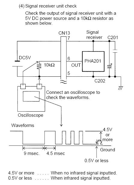
Brand gudie type name link. Eduard photo etched parts. Route lead wire into wiring space. Route sensor into evaporator space. Route lead wire into wiring space.
Gallery of Ss610e Wiring Diagram