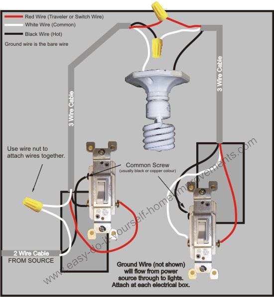
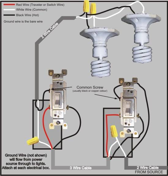
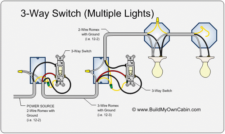
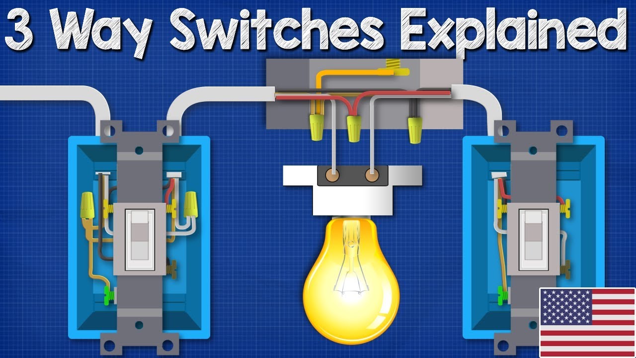
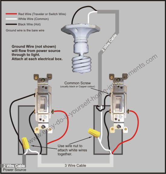
Red wire power or hot wire black wire power or hot wire white wire neutral bare copper ground. Three wire cable runs between the switches and 2 wire cable runs to the light.

Wiring 4 Way Switch Diagram Wiring Diagram
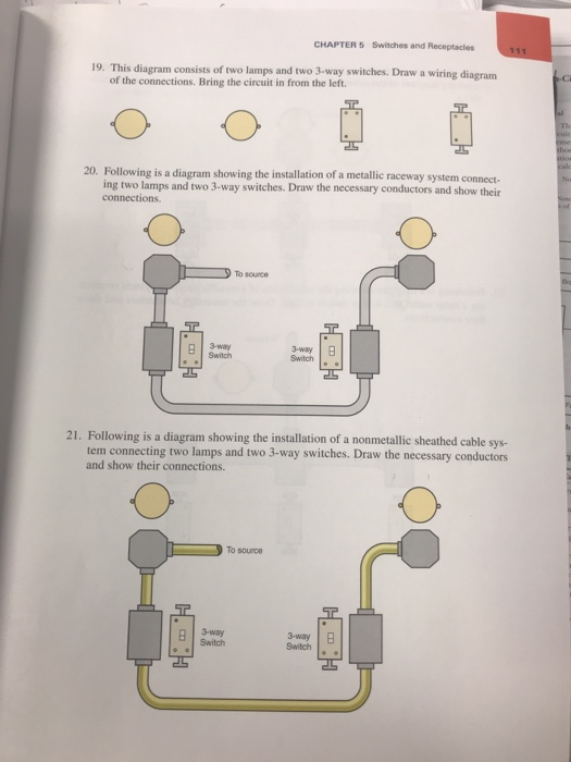
Show wiring diagram for 3 way switch. Take a closer look at a 3 way switch wiring diagram. Typical 3 way switch wiring nm cable in the 1st diagram below a 2 wire nm cable supplies power from the panel to the first switch box. See alternate 3 way switch wiring configuration for another way 3 way switches may be wired. Once your boxes are in place you can start the process of installing and wiring the switches themselves. The ground wire goes through both switch boxes and the ceiling light box and it is connected at all junctions except the light with a pigtail short piece of wire and wire connector. Regardless of what 3 way switch wiring diagram youre following youll need to use a 3 wire cable to connect the two 3 way light.
Wiring diagram 3 way switch with light at the end in this diagram the electrical source is at the first switch and the light is located at the end of the circuit. All three way switch and 2 way switch wiring diagrams have the same basic components. If you are trying to troubleshoot a 3 way switch operation then you will need to identify the function of each wire. If you have any problems with these switches it may be best to call an electrician. The diagrams below show the conventional wiring for 3 way switches. The cable wires lead to a second 3 way switch box on the right side.
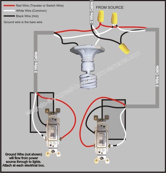
Pick the diagram that is most like the scenario you are in and see if you can wire your switch. With these diagrams below it will take the guess work out of wiring. Black wire power or hot wire white wire neutral bare copper ground. The black hot wire connects to the far right switchs common terminal. In this diagram power enters the fixture box. This might seem intimidating but it does not have to be.
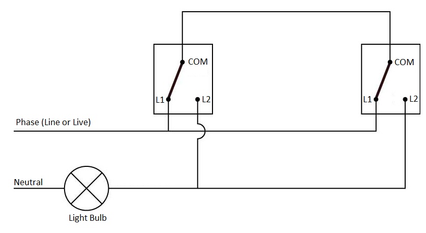
Red and blue wires link traveler terminals of both switches. Components of 3 way switch wiring. This 3 way light switch wiring diagram shows how to do the light switch wiring and the light when the power is coming to the light fixture. Unfortunately not all 3 way switches are wired the conventional way. A 3 wire nm connects the traveler terminals of the first and second 3 way switch together. 3 way switch wiring diagram 2 above shows the electric circuit power source comes into the light fixture box.
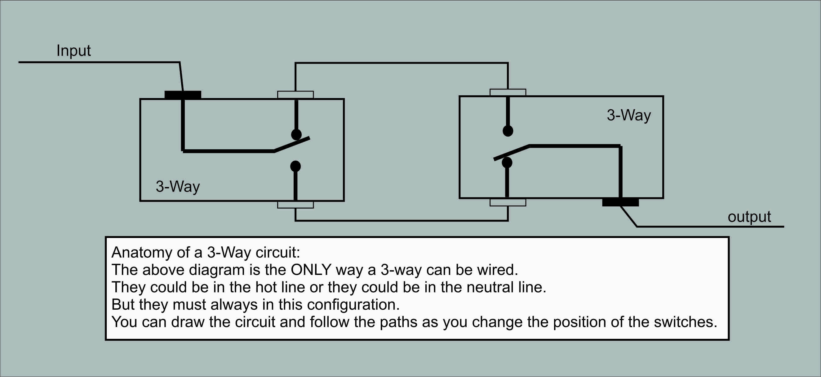
Run new cable romex between the 3 way switches. The black and red wires between sw1 and sw2 are connected to the traveler terminals. 3 way switch wiring diagram 1 above shows that the electric circuit source power is located at the left side 3 way switch box. Wires consisting of a line a load a neutral a pair of travelers and two 3 way switches. 3 way switch wiring diagram. Refer to the above 3 way switch diagram.
When wiring a 3 way switch circuit all we want to do is to control the black wire hot wire to turn on and off the load from 2 different locations. The black line wire connects to the common terminal of the first 3 way switch. Two three way switches control one light with the electric power coming through the first switch flowing to the second switch and then to the light fixture.
Gallery of Show Wiring Diagram For 3 Way Switch