Typical layout wiring diagram. A wiring diagram usually gives assistance nearly the relative approach and accord of devices and terminals on the devices to put up to in building or servicing the device.

Page 18 Snowflake
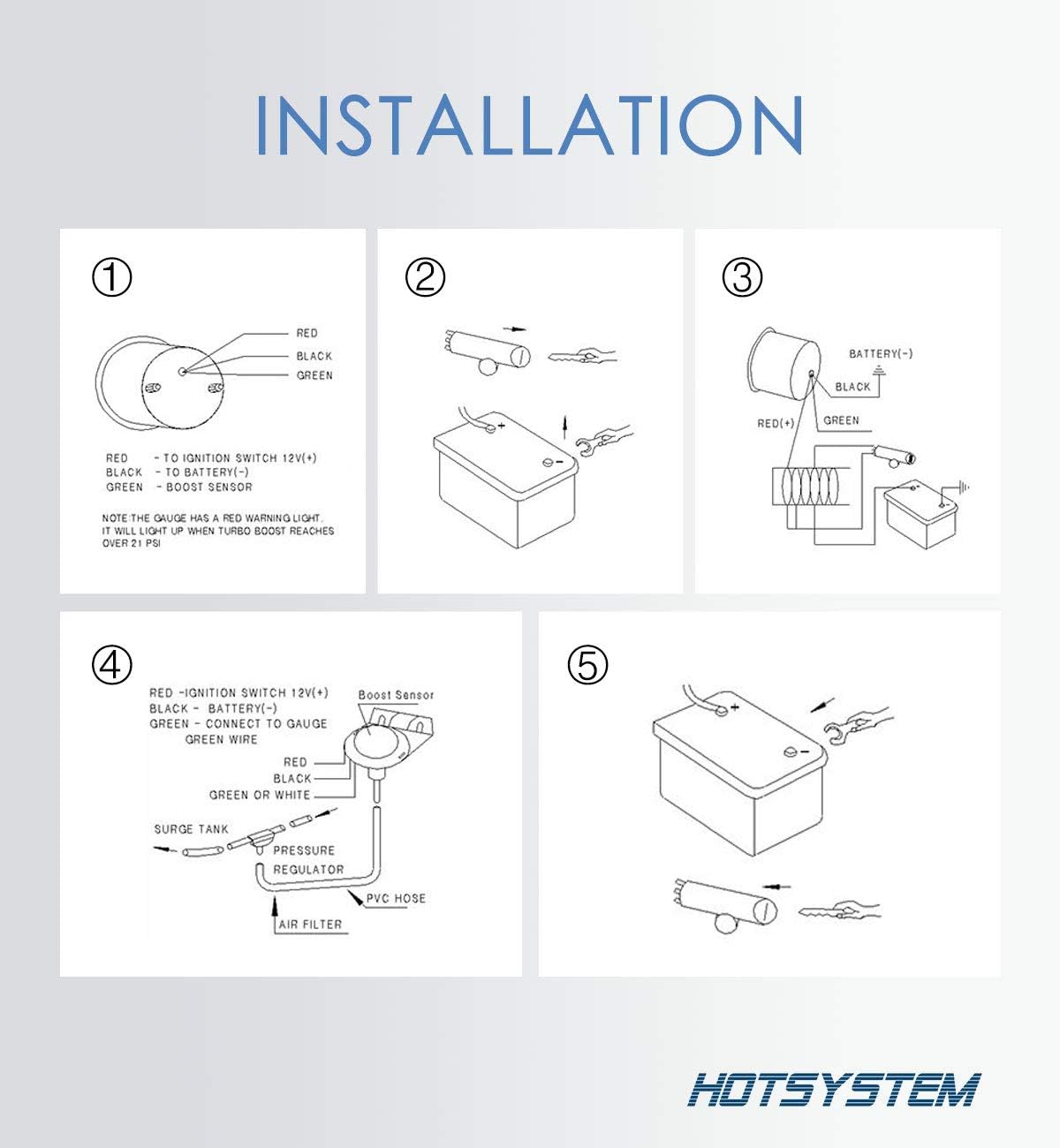
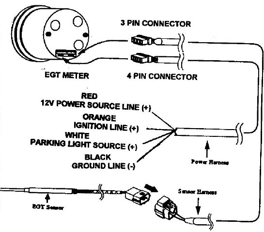
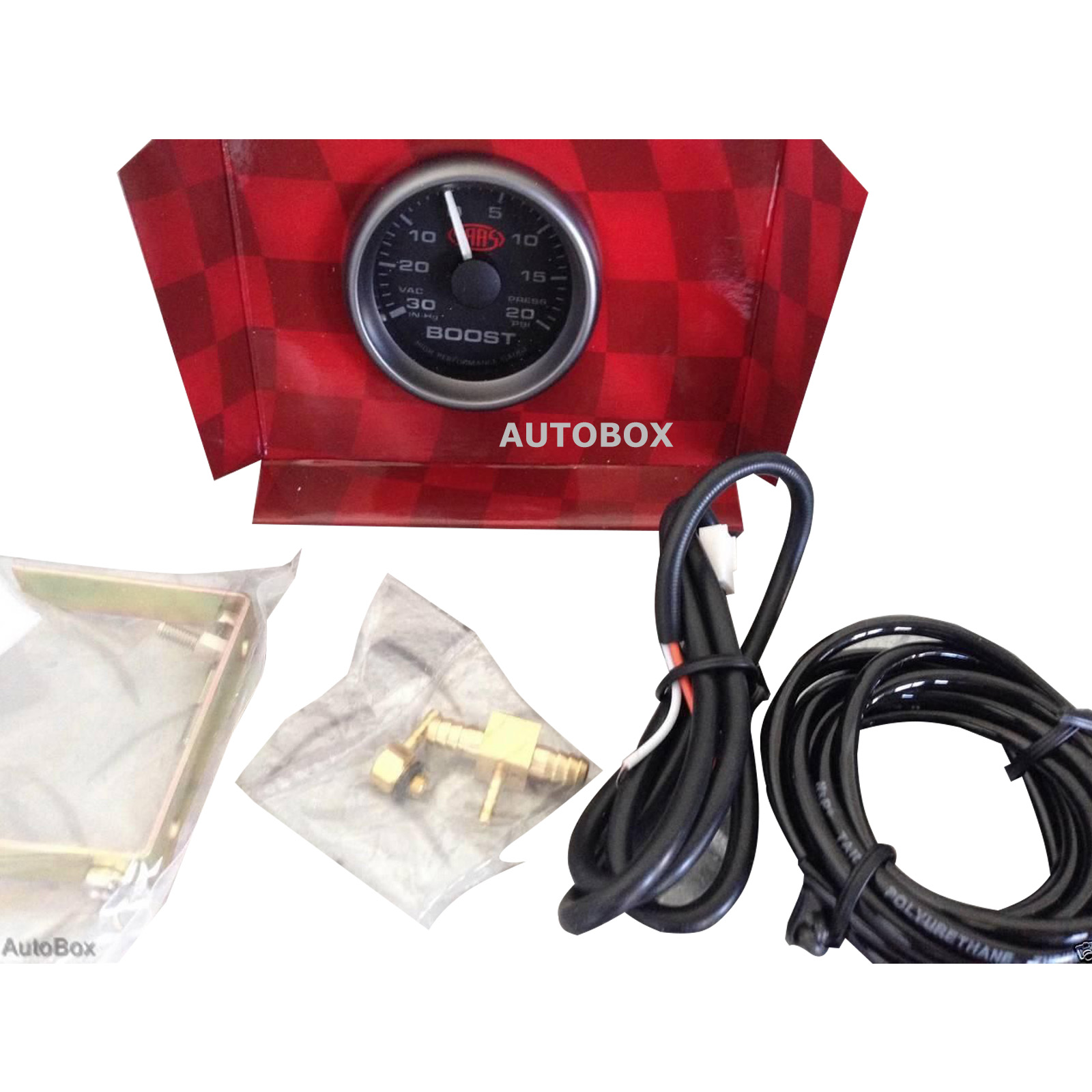
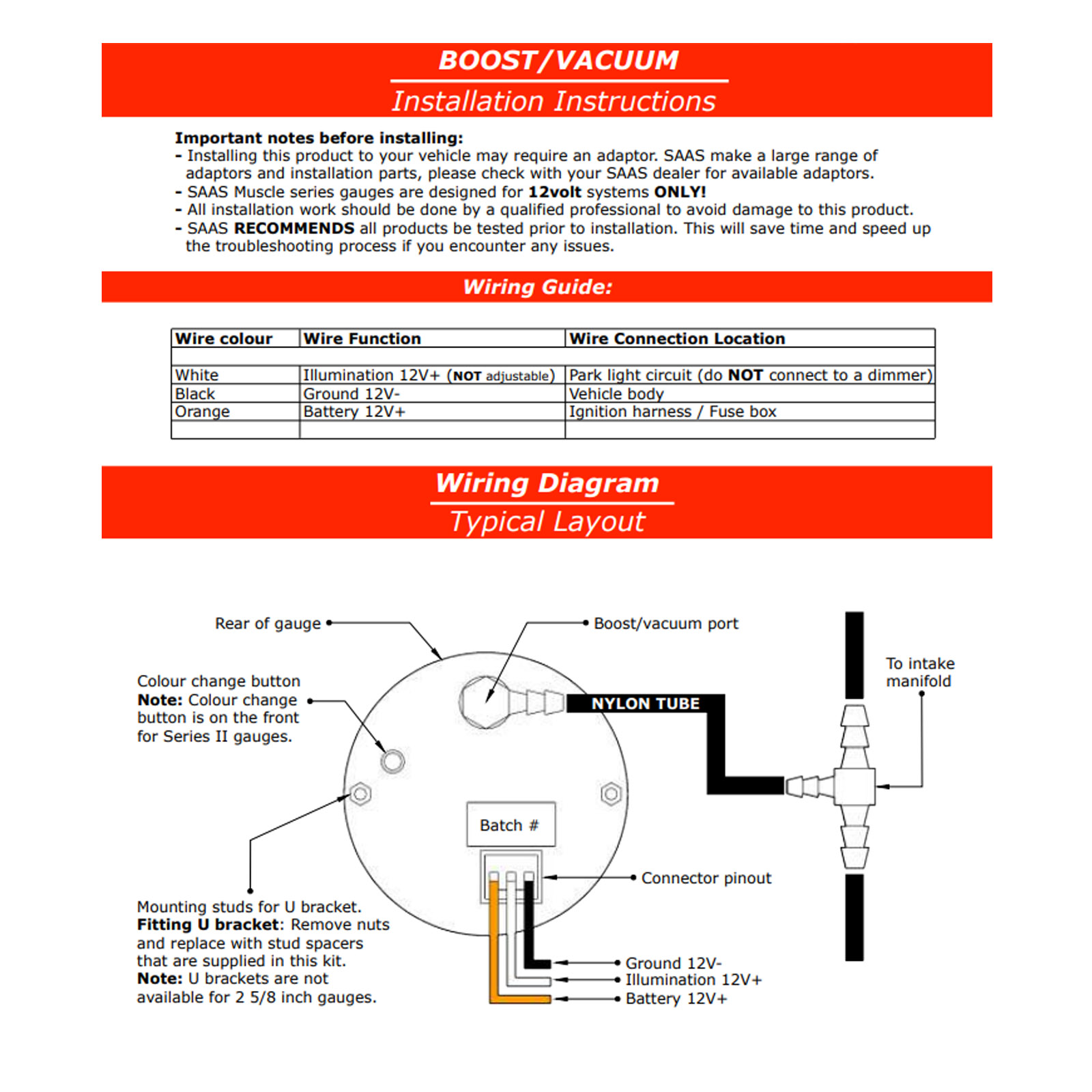
Saas boost gauge wiring diagram. Heres the wiring instructions for the saas gauges. Parts list common parts 1 pressure or vacuumboost gauge 1 lamp socket 1 light bulb 1 vdo. Remove nuts and replace with stud spacers that are supplied in this kit. More than one gauge and you wish to allow programming from a single push button connect the communication link wires together see wiring diagram on page 2. The gauge id of all linked gauges will need to be set to unique numbers. From the latest in dash mounted speedo and tacho to dual reading gauges perfect for that 4wd fit out even carling type gauges that mount in your spare switch panel slots.
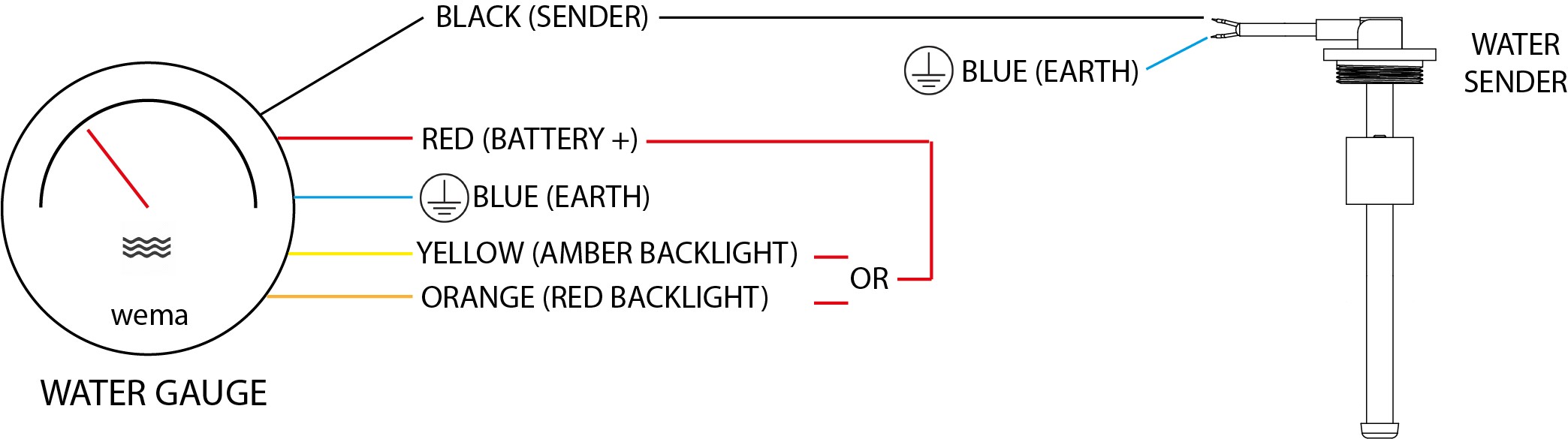
This will save time and speed up the troubleshooting process if you encounter any issues. Saas trax series gauges are designed for 12volt systems only. Saas recommends all products be tested prior to installation. Rear of gauge battery 12v ground 12v illumination 12v mounting studs for u bracket. Wiring diagram colour change button note. If your gauge is part of a multi gauge system ie.
Auto gauge boost gauge wiring diagram wiring diagram is a simplified gratifying pictorial representation of an electrical circuit. Saas has long been supplying the automotive aftermarket with a wide range of performance gauges. Installation and troubleshooting guide trax by saas dual boost 0 30 psi and volts 8v 18v gauges sg613020 trax by saas oil presswater temp install guide installation and troubleshooting guide trax by saas oil pressure 140 psi and water temp 40 120 deg gauges. Colour change button is on the front for series ii gauges. Check out my store on 4x4 camping and adventures httpswww. Hey everyone in this video i show you how to install the saas pillar pod with gauges going through the install to a working unit.
Run a wire from the other lamp socket terminal to a good ground such as the chassis. How to install a boost gauge prosport boost gauge unboxing and install duration. See diagram e 5. It shows the components of the circuit as simplified shapes and the capacity and signal associates with the devices. This is for a sub who wants to know about the saas gauges wiringi hope it helps. U brackets are not available for 2 58 inch gauges.
Run a wire from one terminal on the gauge lamp socket to the lighting circuit 12v source such as a light switch. All installation work should be done by a qualified professional to avoid damage to this product.
Gallery of Saas Boost Gauge Wiring Diagram