Motorised switch cl ncl g q1 q2 ats automatic transfer switch protection arent shown on the following schemes. The atys range socomec general catalogue.
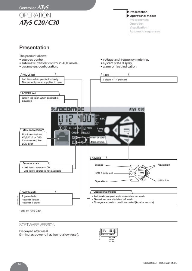
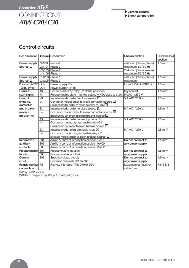
09 Operating Instruction C20 C30
Socomec atys 3s wiring diagram. It shows the components of the circuit as simplified shapes and the capability and signal friends between the devices. On led manueldefaut red ensure that the emergency handle is. 541 892 c 1. In automatic mode they enable the monitoring of and the on load changeover between two power supply sources in accordance with. Atys 836 a atys 599 c socomec products. In addition to the functions offered by the atys s the atys d s incorporates supply redundancy without the need for additional wiringthis is obtained by integrating a double supply 2 independent supplies directly within the product.
Wiring and if ok power up the product. Control position 0 c 4. Atys r and atys d are 3 or 4 pole remotely operated motorised transfer switches with positive break indication. S1 kva sg kva comut 044 a t1 ncl q1 cl q2 ats g comut. They enable the on load transfer of two three phase power supplies via remote volt free contacts from either an external automatic controller using pulse logic or a switch. 4 atys s sd réf.
Atys m 3s is equipped with two independent 230 vac 176 288 vac 5060 hz 45 65 hz power inputs. Atys d m devices are 2 pole or 4 pole transfer switches that are remotely controlled using volt free contacts from an external controller. They incorporate all the functions offered by the atys t and g as well as functions designed for power management and communication. General safety instructions this manual provides instructions on safety connections and operation of the atys s and atys sd motorised changeover switches manufactured by socomec. Control position i 2. They are intended for use in low voltage power supply systems where a brief interruption of the load supply is acceptable during transfer.
Socomec atys 3s wiring diagram transfer switching technology by socomec atys 125 3200a youtube socomec atys 3s wiring diagram wiring diagram is a simplified okay pictorial representation of an electrical circuit. The atys range key features. They are modular products with positive break indication. Atys p are 3 or 4 pole automatic transfer switches with positive break indication. Power supply i 230 vac. Control position ii 3.
The atys family product range8 31. 4 technical information standard diagrams transfer between 2 sources 2 bus bars first type of architecture.
Gallery of Socomec Atys 3s Wiring Diagram