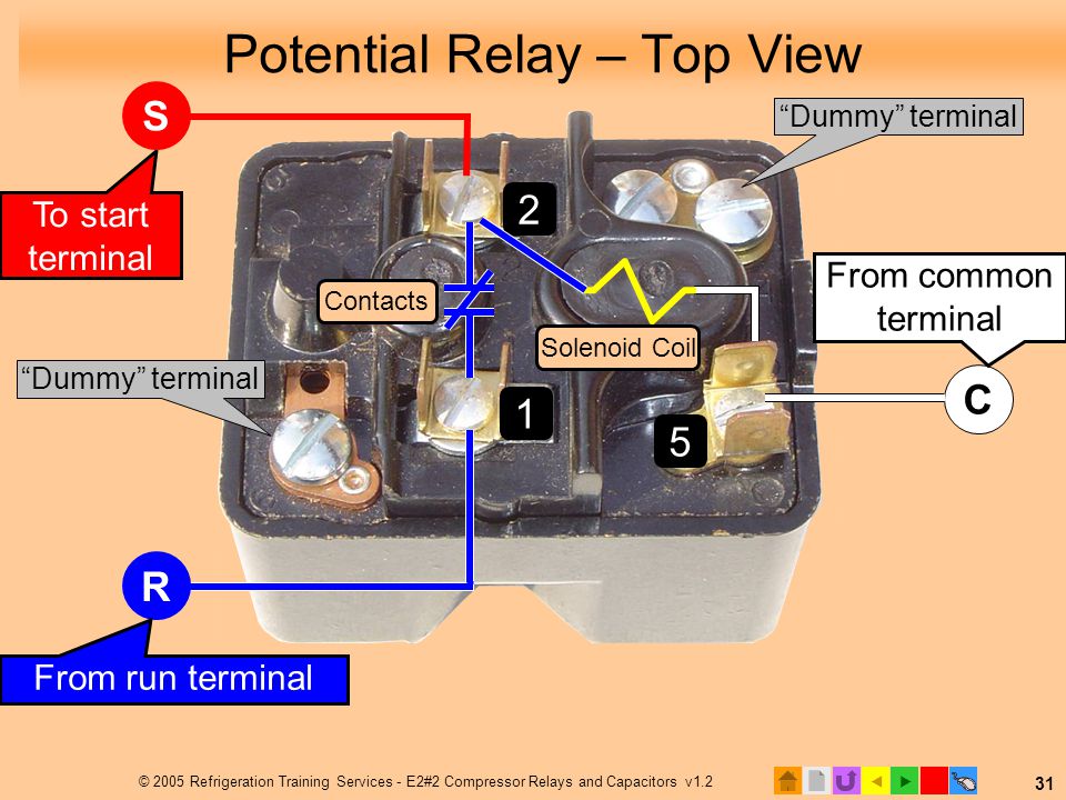
I show the coil and how to measure resistance values for diagnosing the coil or contactor tabs while using a multimeter. I explain how it controls the start capacitor after the compressor starts.

16104 3arr3j3g3 Start Potential Relay Rva8as3l
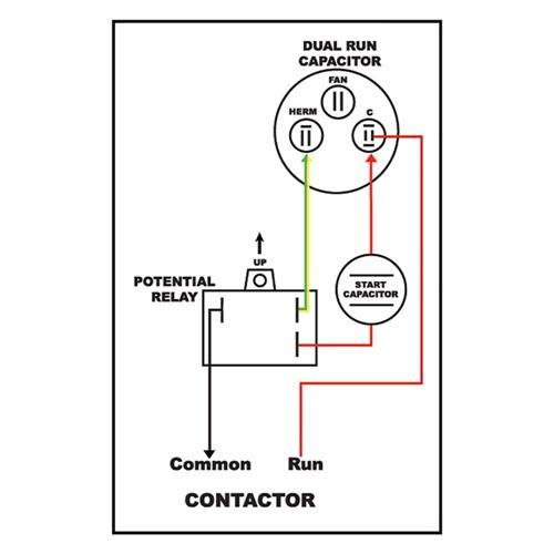
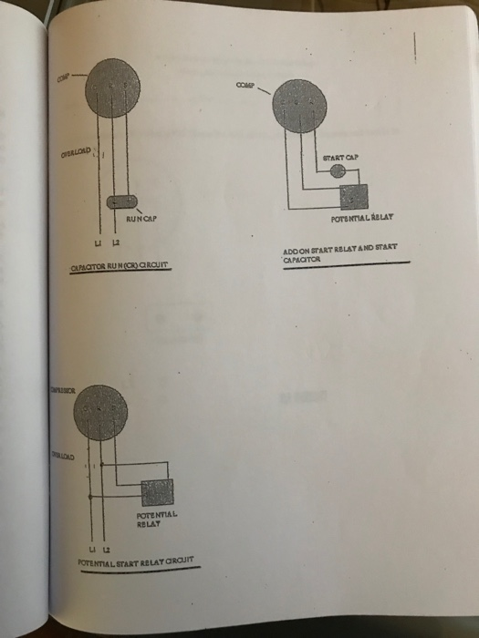
Potential relay start capacitor wiring diagram. This video is part of the heating and cooling series of training videos made to accompany my websites. Each part should be set and connected with different parts in particular way. Potential relay wiring diagram compressor potential relay wiring diagram copeland potential relay wiring diagram mars potential relay wiring diagram every electrical arrangement consists of various distinct components. The purpose of this booklet is to dem onstrate how to wire a. The relay disconnects the start capacitor from the motors electrical circuit once the motor has reached operational speed. If not the structure wont function as it should be.
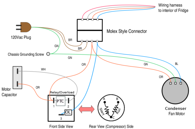
Understanding basic electrical. Test the start relay overload capacitor ptc. Potential relay wiring diagramac capacitor wiring relay wiring with starting and running capacitor potentialrelaywiring voltagerelaywiring relaywir. Accordance with the position of the capacitors and relay shown on the wiring diagram. The start capacitor is removed from the circuit by a relay called the potential relay. The potential relay is normally closed and it opens when a sufficient pickup voltage is present between the 5 and 2 terminals on the relay.
It is very easy to miswire a compressor but the results can be deadly. The back emf voltage generated across the start winding causes a small current to flow in the start winding and potential relay coil because they are in the same circuit. A start capacitor kit contains a start capacitor relay and wires. The start capacitor gives the motors windings an electric boost during the start up phase. This guide even consists of recommendations for additional provides that you might need to be able to complete your tasks. Potential relay start capacitor run motor with capacitor diagram potential relay wiring diagram.
When the back emf has built up to a high enough value referred to as pick up voltage the contacts between terminals 1 and 2 will be picked up opened. This is the wiring of the potential relay. Explaining the differences between current relays and potential relays and their role in starting compressors. Wiring diagram also provides beneficial recommendations for tasks which may need some extra equipment.
Gallery of Potential Relay Start Capacitor Wiring Diagram