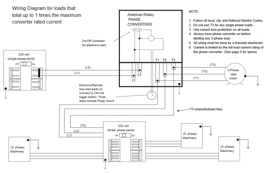
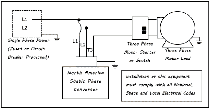
It reveals the parts of the circuit as streamlined forms and the power and signal links in between the devices. Do not use t3 for any single phase loads.
Phase Converters
Phase converter wiring diagram. Our phase converters are built to last using the highest quality standards and only the highest quality components. Above is the field or power wiring diagram. Other load voltages require a transformer after the three phase panel. It shows the elements of the circuit as simplified shapes and the power and also signal connections between the tools. A wiring diagram is a streamlined standard photographic depiction of an electric circuit. 3 phase idler motor t1 t2 t3 wiring diagram for paralleling multiple phase converters using a transfer switch.
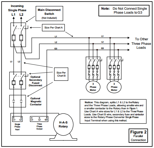
If you need a different configuration just let us know. If you look closely you will see all the basic elements from the very simple static phase converter diagram shown earlier. A wiring diagram is a simplified traditional pictorial depiction of an electric circuit. All wiring must be done by a licensed electrician. A wiring diagram is a streamlined standard photographic depiction of an electrical circuit. It reveals the elements of the circuit as streamlined forms and also the power as well as signal connections between the devices.
Assortment of static phase converter wiring diagram. Follow all local city and national electric codes. Contactor c1 has replaced the drum switch and contactor c2 has replaced the momentary pushbutton for connecting the starting capacitor between l2 and l3. Our three phase converters are ac single to three phase 208v 220v 240v 440v 460v and 480v converters. Collection of american rotary phase converter wiring diagram. Collection of 3 phase rotary converter wiring diagram.
Gallery of Phase Converter Wiring Diagram